Quantcast
Channel: Engineering Photos,Videos and Articels (Engineering Search Engine)
Viewing all 96 articles
Browse latest View live

Dielectric Phenomena and Polarization

$
0
0

The dielectrics have the property of both temporary and permanent absorption of electrical charges and property of conduction. When a voltage is applied to a dielectric, forces on the positive and negative charges inherent in the particles which make up the dielectric tend to orient the particles in line with the applied field. Some dielectric materials have molecules that have uneven number of atoms, that is, having asymmetrical arrangement of charges. 


When such  a molecule is placed in an electrical field, it will migrate in an electric field, thus become polarized with the electric field.

Such a molecule is called a dipole. Dipoles play an important role in the electrical characteristics of the insulation. A dipole may be represented by a particle having small positive charge at one end and a small negative charge at the other end. When these dipoles are subjected to DC voltage, they are polarized and become aligned with respect to positive and negative polarity of the DC voltage. This phenomenon is known as dipole polarization. Polarization phenomenon is influenced strongly by the material properties, structure, and condition of the insulation.

On the other hand, charged particles, that is, particles with positive and negative charges, which are not interrupted by interfacial barriers, and can travel through the dielectric from one electrode to the other, constitute the leakage current, and are not part of the polarization phenomenon.

After a time when the applied voltage is removed from the dielectric, the polarized molecules will eventually revert to their initial random arrangement so that the polarization approaches zero. The time it takes for the polarization to drop to zero when the dielectric is short-circuited is known as relaxation time. It should be noted that the large dielectrics have a much longer relaxation time, and appropriate measures should be taken to discharge the released energy (voltage and current) to ground, which is given by the polarized molecules when they revert to their original state.

Compressors

$
0
0


Compressors

Purpose:
To give a basic knowledge about the different types of compressors.

 This training Manual is limited to mechanical description of compressors. The control philosophies are mentioned sometimes to give a better understanding of the machines.


1     Introduction
2     Compression Methods
3     Positive displacement compressors
3.1        Reciprocating compressors
3.1.1     Mechanical Piston Reciprocating Compressor
3.1.1.1    Components and Constructions
3.1.1.2    Frame lubrication
3.1.1.3    Cooling
3.1.2     Diaphragm Compressors
3.1.2.1    Construction and Principle of Operation
3.1.2.2    Head Integrity Detection System
3.2        Rotary compressors
3.2.1     Sliding vane compressor
3.2.2     Helical lobe compressor (screw compressor)
3.2.3     Straight lobe compressor (blower)
4     namic Compressors
4.1        Ejector
4.2        Centrifugal Compressor
4.2.1     Arrangement
4.2.2     Mechanical components


1       Introduction

Compression of gas has one basic goal to deliver gas at a pressure higher than that originally existing.  The inlet pressure level can be any value from a deep vacuum to a high positive pressure.  The discharge pressure can range from sub atmospheric levels to high values in the tens of thousands of pounds per square inch.  The fluid can be any compressible fluid, either gas or vapor, and can have a wide molecular weight range.  Applications of compressed gas vary from consumer products such as the home refrigerator, to large complex petrochemical plant installations.

2       Compression Methods

Compressors have numerous forms, the exact configuration being based on the application.  The are two basic compression modes: positive displacement and dynamic.  The positive displacement mode of compression is cyclic in nature, in that a specific quantity of gas is ingested by the compressor, acted upon, and discharged, before the cycle is repeated.  The dynamic compression mode is one in which the gas is moved into the compressor, and discharged without interruption of the flow at any point in the process.  Figure 1 diagram shows the relationship of the various compressors by type.  Figure 2 shows the typical application range of each compressor.


                                    Figure 1

Figure 2

3       Positive displacement compressors

3.1      Reciprocating compressors

Reciprocating compressors are manufactured into different types and styles.  The most recognizable types are:
·         Mechanical piston Reciprocating compressor
·         Diaphragm compressor

3.1.1     Mechanical Piston Reciprocating Compressor

The reciprocating compressor is probably the best known and the most widely used of all compressors.  It consists of a mechanical arrangement in which reciprocating motion is transmitted to a piston which is free to move in a cylinder.  The displacing action of the piston, together with the inlet valve, causes a quantity of gas to enter the cylinder where it is in turn compressed and discharged.  Action of the discharge valve prevents the backflow of gas into the compressor from the discharge line during the next intake cycle.  When the compression takes place on one side of the piston only, the compressor is said to be single acting.  The compressor is double acting when the compression takes place on each side of the piston.  When a single cylinder is used or when multiple cylinders on a common frame are connected in parallel, the arrangement is referred to as a single stage compressor.  When multiple cylinders on a common frame are connected in series, usually through a cooler, the arrangement is referred to as a multistage compressor. Figure-3,4,5 give some examples of reciprocating compressors.


                        Figure-3


 Figure-4
              

    Figure-5

3.1.1.1       Components and Constructions

Cylinders
Cylinders for compressors used in the process industries are separable from the frame.  The are attached to the frame by way of an intermediate part known as the distance piece.  All cylinders are equipped for cooling, usually by means of water jacket or air fins.  Larger cylinders normally have enough space for clearance pockets.  A clearance pocket is used for capacity control in some compressor.  Figure 6 is an illustration of a cylinder with an unloading pocket in the head.  
                                         
      
                          Figure-6
Pistons and Rods
The piston must translate the energy from the crankshaft to the gas in the cylinder.  The piston is equipped with a set of sliding seals referred to as piston rings.  Rings are made of a material that must be reasonably compliant for sealing, yet must slide along the cylinder wall with minimum wear.  Figure 7 shows a piston with piston rings.  In some processes, it is preferred to use a labyrinth piston (See Figure 8).  The piston rod is threaded to the piston and transmits the reciprocating motion from the crosshead to the piston.


Figure 7     


     Figure 8
Valves
The compressor cylinder valves are of the spring-loaded, gas-actuated. Two of the many basic valve configurations are depicted in Figure 10 & 11.  Damaged valves can cause noticeable decreases in compression efficiency.  The valves can normally be removed and serviced from outside the cylinder without dismantling any other portion.  The inlet and discharge valves should not be physically interchangeable.  

Figure10                    


                                     Figure 11
Distance piece
The distance piece is a separable housing that connects the cylinder to the frame.  The distance may be opened or closed and may have multiple compartments.  The purpose of the distance piece is to isolate that part of the rod entering the crankcase and receiving lubrication from the part entering the cylinder and contacting the gas.  This prevents lubricant from entering the cylinder and contaminating the gas. Some typical distance piece arrangements are shown in Figure 12.


Figure 12
Rod Packing
A packing is required whenever piston rod protrude through compressor cylinder and distance piece.  The packing may consist of a number of rings of packing materials and may include a lantern ring (see Figure 13).  If cooling of packing is required, the packing box may be jacketed for liquid coolant.


Figure 13

Crankshaft and bearing
The crankshaft is drilled with passages to allow for pressure lubrication of the bearings and crosshead.  Figure 14 shows a drilled crankshaft.  The main and connecting rod bearings are mostly split-sleeve, insert type.  Figure 15 shows a split sleeve bearing caps.


Figure 14     

                                              Figure 15

3.1.1.2       Frame lubrication

The pressurized lubrication system is a more elaborated lubrication method (see Figure 16) the system has a main oil pump, either crankshaft or separately driven, a pump suction strainer, a cooler when needed, a full-flow oil filter and safety instrumentation.


Figure 16

3.1.1.3       Cooling

For large process gas compressors, forced cooling through the cylinder barrel and heads is most common.  If water is used, it is very important that clean treated water be used.  The purpose of cylinder cooling is to equalize cylinder temperatures and prevent heat buildup.  This cooling only removes the frictional heat, the heat of compression is removed by the inter- or aftercoolers.


3.1.1.4 Capacity control
Capacity control is so important.  The reciprocating compressor cannot self-regulate its capacity against a given discharge pressure; it will simply keep displacing gas.  The four famous capacity control methods are bypass, suction throttling, suction valve unloading and clearance pockets. 
One of the simplest methods of controlling is to bypass, or recycle the compressed gas back to the compressor suction.  This is accomplished by piping from the compressor discharge line through some type of control valve and going back to the compressor suction line.  In addition to being simple, this system also has the advantage of being infinitely controllable. 
Probably the most common method of controlling compressor capacity is via suction valve unloading.  The technique here is to physically keep the cylinder from compressing gas by maintaining an open flow path between the cylinder bore and the cylinder suction chamber.  The cylinder will take in gas normally; however, instead of completing the normal cycle of compression and discharge, the cylinder will simply pump the gas still at suction pressure back into the suction chamber via this opening pathway.
Although not very widely used, suction throttling is another method of controlling the capacity of a reciprocating compressor.  The technique is to reduce the suction pressure to the compressor by limiting or throttling the flow into the cylinder.  Suction throttling has its limitations. It takes a fairly dramatic reduction in suction pressure to give any sizeable reduction in capacity.  Additionally, as the suction pressure is reduced and the discharge pressure held constant, the compression ratio is increased.  This causes higher discharge temperatures and also higher rod loads.
Clearance pocket is essentially an empty volume, typically in the outer head of the cylinder, with a valved passage to the cylinder bore (see Figure 17).  During normal operation, the valve is closed and the cylinder operates at full capacity.  For reduced capacity operation, the valve is opened, and the cylinder capacity is reduced by the effect of added clearance.


Figure 17

3.1.2        Diaphragm Compressors

The diaphragm compressor (Figure 18) is designed to compress gases without the use of a dynamic seal. This allows the unit to handle gases that cannot be processed with an ordinary compressor. It can be used for gases that demand the ultimate in cleanliness or for hazardous gases, this with no gas pollution.
The diaphragm compressor has a conventional crankshaft, connecting rod and piston. The piston, however, does not compress gas. It forces hydraulic fluid against a flexible metal diaphragm. The diaphragm compresses the gas by deforming against a smooth, domed contour, eliminating the need for a dynamic seal.

                                                Figure 18

3.1.2.1       Construction and Principle of Operation

The diaphragm compressor has a conventional crankshaft, connecting rod and piston. The piston, however, does not compress gas. It forces hydraulic fluid against a flexible metal diaphragm. The diaphragm compresses the gas by deforming against a smooth, domed contour, eliminating the need for a dynamic seal.
Upon each complete ascending and descending stroke of the piston, a compensating pump actuated by an eccentric on the shaft sends a quantity of fluid greater than the quantity that escapes between the piston and the cylinder and ensures the application of the diaphragm to the gas plate, thereby reducing the dead space to the minimum.
The excess oil expelled by the compressor is evacuated by a calibrated valve called pressure limiter and returns to the casing. The direction of the oil circulation, casing-compensator, compensator-cylinder, and cylinder casing ensured by the non-return valves and the pressure limiter.
The piston moves in the cylinder and pushes the hydraulic fluid in the head producing an oscillating movement of the diaphragm group (Figure 19).
The diaphragm group consists of three diaphragms clamped and seated at the periphery between the gas plate and oil plate (Figure 20).
The oil plate has the role of distributing the hydraulic fluid uniformly under the diaphragms and the gas plate. The gas plate contains the suction and the discharge valves. The discharge valve is located at the center of the gas plate for optimum capacity. The two plates are specially contoured on their internal faces and their assembly forms the compression chamber. Their profile is carefully designed so as to minimize the stress in the diaphragms.
           
                                                
 Figure 19
     
                                                       
 Figure 20

3.1.2.2       Head Integrity Detection System

Running a diaphragm compressor with a cracked or broken diaphragm will damage the machined surfaces of the upper or lower plates, pollute handled gas and create a problem of gas leakage to atmosphere. It is important, should a diaphragm break, the compressor must be stopped immediately.
For these reasons the compressor is fitted with a diaphragm crack detection system. The system uses 3 diaphragms sandwiched together. Should a diaphragm either on the oil or the gas side cracks, then the pressure between the intermediate diaphragm and the cracked diaphragm will rise. An instrument tapping from this intermediate diaphragm is fed to a pressure switch set to sense rising pressure. This switch is in turn connected to the compressor control gear which shuts down the drive motor.
Intermediate diaphragm has a pressure-tapping slot or grooves located across sealing area at diaphragm periphery.
When the 3 diaphragms are located together, the tapping slot or groove in the intermediate diaphragm is positioned into circumpherencial grooves machined between gas and oil plate to guide the any leakage to the detection system.
Figure 21 & 22 show a diaphragm crack detection system.

                                                                        Figure 21

                                                                        Figure 22

3.2      Rotary compressors

3.2.1        Sliding vane compressor

This type of compressor has a rotor eccentrically mounted inside a cylinder, which is mostly water jacketed for cooling purpose.  The rotor is fitted with blades that are free to move radially in and out of longitudinal slots.  These blades are forced out against the cylinder wall by centrifugal force. Figure 23 shows the sliding vane compressor and the operation principle.


                        Figure23                                                   

3.2.2        Helical lobe compressor (screw compressor)

Helical lobe compressors (Figure 25) are rotary positive displacement machines in which two intermeshing rotors, each with helical form, compress and displace the gas.  The rotor with the lobe is called a male rotor and the rotor with the interlobe is called a female rotor.  Figure 26 shows a typical screw compressor rotor combinations.   In some types, oil or liquid is injected inside the compressor area to cool down the compressed gas.  This is because some gases can polymerizes when it is compressed due to increase in temperature.  The screws are kept without touching due to the timing gears (see Figure 27).  Because screw compressor is a positive displacement machine, the most advantageous method of achieving capacity or volume flow control is obtained by variable speed motor or installing a bypass.


    Figure 25

Figure 26                                   


     Figure 27

3.2.3         Straight lobe compressor

Straight lobe compressors are rotary positive displacement machines in which two straight mating lobed impellers trap gas and carry it from intake to discharge.  This type of compressor is mostly used in pneumatic conveying systems.  In petrochemical industry, it can be used to convey powder and pellets.  Figures 28 to 29 shows a typical blower and the principle of operation.


             Figure 28


Figure 29

4          Namic Compressors

4.1      Ejector

Ejectors are principally used to compress frompressure below atmospheric to a discharge close to atmospheric.  The ejector has no moving parts and it is simple and it has no wearing parts  (see Figure 30).  The ejector is operated directly by a motive gas or vapor source.  Air and steam are probably the most common of the motive gases.  The ejector uses a nozzle to accelerate the motive gas into the suction chamber where the gas to be compressed is admitted at right angles to the motive gas direction.  In the suction chamber, the suction gas is entrained by the motive fluid.  The mixture moves into a diffuser where the high velocity gas is gradually decelerated and increased in pressure.


                           Figure-30

4.2      Centrifugal Compressor

A centrifugal compressor is a continuous flow unit in which the mechanical action of rotating vanes or impellers imparts velocity and pressure to the flowing medium.  The velocity energy is then converted to additional pressure.  See Figure 31& 32 for typical centrifugal compressors.


Figure-31  
                                                             Figure-32                                                  

4.2.1        Arrangement

One type of compressor is an overhung type centrifugal compressor (see Figure 33).  It is basically an overhung style machine mounted on a gearbox and uses the gear pinion shaft extension to mount an impeller.
Another type is a multi-stage centrifugal compressor.  In this type, many impellers are attached to the rotor. This type of compressors is one of the most important compressors in the industry today (see Figure 34).
Figure 35shows a schematic layout of integrally geared compressor.  It consists of three impellers, the first located on one pinion, which would have a lower speed than the other pinion that has mounted the remaining two impellers.


Figure 33                                                     


  Figure 34
                                         
 
Figure-35

4.2.2        Mechanical components

Casings
The casing for centrifugal compressor can be horizontal or vertical split.  The horizontal split casing is generally used for low-pressure operation relative to vertical split casing. Figure 36 and 37 shows a vertical and horizontal split compressor.  Normally, all the connections such as the suction and discharge nozzles are arranged on the bottom section of the casing so that the upper section can be easily removed for maintenance work.


   Figure 36                                                 
 Figure 37
Internals / diaphragms
The internal flow-conducting components comprise an inlet ring, the intermediate diaphragms and the discharge volute (see Figure 38).  The diaphragms form diffuser for each impeller and the return duct leading to the intake of the next impeller.  The discharge volute conducts the gas to the discharge nozzle of the compressor.

    
 Figure-38

Shaft and impellers
The rotor consists of the shaft, impellers, shaft sleeves, a balancing piston and the thrust collar for the axial bearing.  The number and size of the impeller depends on the process requirements.  Figure 39 shows a shaft and impellers together.
      
Figure-39
                                      
Bearings
Radial bearings or journal bearings are usually pressure lubricated.  Most compressor use two bearings on opposite ends of the rotor assembly or on the overhung design located adjacent to each other between the drive coupling and the impeller. It is highly desirable for ease maintenance to have the bearing horizontal split (see Figure 40).  Double-acting thrust bearings are also there to absorb the axial forces.  There are tilting pad type and should be suitable for both directions of rotation (see Figure 41).  Magnetic bearings maybe employed instead of oil lubricated bearings for certain applications (see Figure 42). The advantages of magnetic bearing are the reduction of mechanical losses, no supply of oil necessary and the adjustability of the radial and axial positions of the rotors.


Figure 40                         

 
                   Figure 41
                   
                                                    
 Figure 42

Shaft end seals
Many of the gases to be compressed are combustible, explosive, toxic or harmful to the environment, and under no circumstances can these be allowed to enter the atmosphere.  Depending on the service conditions, any of the following seals can be applied:
Labyrinths seals
Oil lubricated mechanical contact seals
Oil lubricated floating-ring seals
Dry-running gas seals

To Be Continued .......

Bases of Maintenance and Testing of Protective Devices

$
0
0

The NEC Articles 210-20, 215-3, 240-1, and 240-3 specify requirements for the protection of electrical equipment and conductors. The Fine Print Note (FPN) to Article 240-1, Scope, states, “Overcurrent protection for conductors and equipment is provided to open the circuit if the current reaches a value that will cause an excessive or dangerous temperature in conductors or conductor insulation.”
To protect against overcurrent conditions, the only way to ensure that circuit breakers, overcurrent relays, and protective devices are working correctly is through regular maintenance and testing of these devices. There are several steps that must be taken in order to establish an effective maintenance program for the breakers and overcurrent protective devices. The first step in correctly maintaining electrical equipment and overcurrent protective devices is to understand the requirements and recommendations for electrical equipment maintenance from various sources.

Examples of such sources include, but are not limited to, the manufacturer’s instructions, NFPA 70B, IEEE Standard 902 (Yellow Book), NEMA AB-4, NETA Specs, NFPA 70E and this book.
The second step in performing maintenance and testing is to provide adequate training and  qualification for employees.

 NFPA 70E, Section 205.1 states, “Employees who perform maintenance on electrical equipment and installations shall be qualifi ed persons … and shall be trained in and be familiar with the specific maintenance procedures and tests required.” The NEC defines a qualifi ed person as “One who has skills and knowledge related to the construction and operation of the electrical equipment and installations and has received safety training on the hazards involved.” It is vitally important that employees be properly trained and qualifi ed to maintain electrical equipment in order to increase the equipment and system reliability, as well as the employee’s safety.
The third step is to have a written, effective EPM program. NFPA 70B makes several very clear statements about an effective EPM program. These statements include
1. Deterioration of electrical equipment is a normal process, but that does not mean that equipment failure is eminent. If unchecked, deterioration will eventually cause equipment malfunction or complete failure. There are several factors that can accelerate the deterioration process, such as the environment, overload conditions, or severe duty cycles. An effective EPM program will help to identify and correct any or all of these conditions.
2. In addition to the deterioration problem, there are several other potential causes of equipment failure. These causes include, but are not limited to, load changes, circuit alterations, improper or misadjusted settings of protective devices, improperly selected protective devices, and changing voltage conditions.
3. With the absence of an effective EPM program, management assumes a greater responsibility for and an increased risk of a serious electrical failure, as well as the consequences.
4. An effective EPM program, that is administered properly, will reduce costly shutdowns and outages, reduce accidents, and save lives.
These programs will identify impending troubles and apply solutions to correct them, before they become major problems that require time consuming and more expensive solutions.

IEEE Standard 902 states: “In planning an EPM program, consideration must be given to the costs of safety, the costs associated with direct losses due to equipment damage, and the indirect costs associated with downtime or lost or inefficient production.”
The forth step is that all maintenance and testing of electrical protective devices must be accomplished in accordance with the manufacturer’s instructions.
NFPA 70E adds to this by stating: “Protective devices shall be maintained to adequately withstand or interrupt available fault current.” It goes on to state, “Circuit breakers that interrupt faults approaching their ratings shall be
inspected and tested in accordance with the manufacturers’ instructions.”
In the absence of the manufacturer’s instructions, the NETA Maintenance Testing Specifications for Electrical Power Distribution Equipment and Systems is an excellent source of information for performing the required maintenance and testing of these devices. However, the manufacturer’s time–current curves would also be required in order to properly test each protective device.
The fifth and fi nal step that will be addressed here is the arc-fl ash hazard considerations. One of the key components of the fl ash hazard analysis, which is required by NFPA 70E and OSHA, is the clearing time of the protective devices, primarily circuit breakers, fuses, and protective relays. Fuses, although they are protective devices, they do not have operating mechanisms that would require periodic maintenance. However, fuses should be inspected to verify that they are in good working condition.
We will address some of the issues concerning maintenance and testing of the protective devices, according to the manufacturer’s instructions. We will also address how protective device maintenance relates to the electrical arc-fl ash hazard.
Molded-case circuit breakers:Generally, maintenance on molded-case circuit breakers is limited to mechanical mounting, electrical connections, and periodic manual operation. Most lighting, appliance, and power panel circuit breakers have riveted frames and are not designed to be opened for internal inspection or maintenance. All other molded-case circuit breakers that are Underwriters Laboratory (UL) approved are factory-sealed to prevent access to the calibrated elements. An unbroken seal indicates that the mechanism has not been tampered with and that it should function as specified by UL or its manufacture.
A broken seal voids the UL and the manufacturers’ warranty of the device.
In this case, the integrity of the device would be questionable. The only exception to this would be a seal being broken by a manufacturer’s authorized facility.
Molded-case circuit breakers receive extensive testing and calibration at the manufacturers’ plants. These tests are performed in accordance with UL 489, Standard for Safety, Molded-Case Circuit Breakers, Molded-Case Switches and Circuit Breaker Enclosures. Molded-case circuit breakers, other than the riveted frame types, are permitted to be reconditioned and returned to the manufacturer’s original condition. In order to conform to the manufacturer’s original design, circuit breakers must be reconditioned according to recognized standards. 
The Professional Electrical Apparatus Recyclers League (PEARL) companies follow rigid standards to recondition low-voltage industrial and commercial moldedcase circuit breakers. It is highly recommended that only authorized professionals recondition molded-case circuit breakers. Circuit breakers installed in a system are often forgotten. Even though the breakers have been sitting in place supplying power to a circuit for years, there are several things that can go wrong. The circuit breaker can fail to open due to a burned out trip coil or because the mechanism is frozen due to dirt, dried lubricant, or corrosion. The overcurrent device can fail due to inactivity or a burned out electronic component.
Many problems can occur when proper maintenance is not performed and the breaker fails to open under fault conditions. This combination of events can result in fi res, damage to equipment, or injuries to personnel.
All too often, a circuit breaker fails because the minimum maintenance (as specified by the manufacturer) was not performed or was performed improperly.
Small things, like failing to properly clean and/or lubricate a circuit
breaker, can lead to operational failure or complete destruction due to overheating of the internal components. Common sense, as well as manufacturers’ literature, must be used when maintaining circuit breakers. Most manufacturers, as well as NFPA 70B, recommend that if a molded-case circuit breaker has not been operated, opened, or closed, either manually or by automatic means, within as little as 6 months time, it should be removed from service and manually exercised several times. This manual exercise helps to keep the contacts clean due to their wiping action and ensures that the operating mechanism moves freely. This exercise, however, does not operate the mechanical linkages in the tripping mechanism (Figure ).
The only way to properly exercise the entire breaker operating and tripping mechanisms is to remove the breaker from service and test the overcurrent and short-circuit tripping capabilities. A stiff or sticky mechanism
can cause an unintentional time delay in its operation under fault conditions.
This could dramatically increase the arc-fl ash incident energy level to a value in excess of the rating of PPE. There will be more on incident energy later.
Another consideration is addressed by OSHA in 29 CFR 1910.334(b)(2) which states:

Principle components of a molded-case circuit breaker. (From Neitzel, D.K., Principle Components of a Molded-Case Circuit Breaker, AVO Training Institute, Inc., Dallas, TX (revision 2007, p. 14).With permission.)

Reclosing circuits after protective device operation. After a circuit is de-energized by a circuit protective device, the circuit may NOT be manually reenergized until it has been determined that the equipment and circuit can be safely reenergized. The repetitive manual reclosing of circuit breakers or reenergizing circuits through replaced fuses is prohibited. Note. When it can be determined from the design of the circuit and the overcurrent devices involved and that the automatic operation of a device was caused by an overload rather than a fault condition, no examination of the circuit or connected equipment is needed before the circuit is
reenergized.

The safety of the employee, manually operating the circuit breaker, is at risk if the short-circuit condition still exists when reclosing the breaker.
OSHA no longer allows the past practice of resetting circuit breaker one, two, or three times before investigating the cause of the trip. This previous practice has caused numerous burn injuries that resulted from the explosion of electrical equipment. Before resetting a circuit breaker, it, along with the circuit and equipment, must be tested and inspected, by a qualified person, to ensure a short-circuit condition does not exist and that it is safe to reset.
Any time a circuit breaker has operated and the reason is unknown, the breaker must be inspected. Melted arc chutes will not interrupt fault currents.
If the breaker cannot interrupt a second fault, it will fail and may destroy its enclosure and create a hazard for anyone working near the equipment.
To further emphasize this point the following quote from the NEMA is provided:

After a high level fault has occurred in equipment that is properly rated and installed, it is not always clear to investigating electricians what damage has occurred inside encased equipment. The circuit breaker may well appear virtually clean while its internal condition is unknown.

For such situations, the NEMA AB4 “Guidelines for Inspection and
Preventive Maintenance of MCCBs Used in Commercial and Industrial Applications” may be of help. Circuit breakers unsuitable for continued service may be identifi ed by simple inspection under these guidelines.

Testing outlined in the document is another and more definite step that will help to identify circuit breakers that are not suitable for continued service.

After the occurrence of a short circuit, it is important that the cause be investigated and repaired and that the condition of the installed equipment be investigated. A circuit breaker may require replacement just as any other switching device, wiring or electrical equipment in the circuit that has been exposed to a short circuit. Questionable circuit breakers must be replaced for continued, dependable circuit protection.
The condition of the circuit breaker must be known to ensure that it functions properly and safely before it is put back into service.

Low-voltage power circuit breakers: Low-voltage power circuit breakers are manufactured under a high degree of quality control, of the best materials available, and with a high degree of tooling for operational accuracy.

Manufacturer’s tests show these circuit breakers have durability beyond the minimum standards requirements. All of these factors give these circuit breakers a very high reliability rating. However, because of the varying application conditions and the dependence placed upon them for protection of electrical systems and equipment as well as the assurance of service continuity, inspections and maintenance checks must be made on a regular basis. Several studies have shown that low-voltage power circuit breakers, which were not maintained within a 5-year period, have an average of a 50% failure rate. Maintenance of these breakers will generally consist of keeping them clean and properly lubricated. The frequency of maintenance will depend to some extent on the cleanliness of the surrounding area. If there were very much dust, lint, moisture, or other foreign matter present then obviously more frequent maintenance would be required. Industry standards for, as well as manufacturers of, low-voltage power circuit breakers recommend a general inspection and lubrication after a specifi ed number of operations or at least once per year, whichever comes fi rst. Some manufacturers also recommend this same inspection and maintenance be performed after the first 6 months of service regardless of the number of operations.
If the breaker remains open or closed for a long period of time, it is recommended that arrangements be made to open and close the breaker several times in succession, preferably under load conditions. Environmental conditions play a major role in the scheduling of inspections and maintenance.
If the initial inspection indicates that maintenance is not required at that time, the period may be extended to a more economical point. 

However, more frequent inspections and maintenance may be required if severe load conditions exist or if an inspection reveals heavy accumulations of dirt, moisture, or other foreign matter that might cause mechanical, insulation, or electrical failure. Mechanical failure would include an unintentional time delay in the circuit breakers tripping operation due to dry, dirty, or corroded pivot points or by hardened or sticky lubricant in the moving parts of the operating mechanism. The manufacturer’s instructions must be followed in order to minimize the risk of any unintentional time delay. Figure  provides an illustration of the numerous points where lubrication would be required and where dirt, moisture, corrosion, or other foreign matter could accumulate causing a time delay in, or complete failure of, the circuit breaker operation.
Medium-voltage power circuit breakers: Most of the inspection and maintenance requirements for low-voltage power circuit breakers also apply to medium-voltage power circuit breakers. Manufacturers recommend that these breakers be removed from service and inspected at least once per year. They also state that the number and severity of interruptions may indicate the need for more frequent maintenance checks. Always follow the manufacturer’s instructions because every breaker is different.


1. Shunt trip device
2. Trip shaft
3. Roller constraining link
4. Trip latch
5. Close cam
6. Stop roller
7. Spring release latch
8. Spring release device
9. Oscillator pawl
19. Reset spring
20. Closing spring anchor
21. Pole shaft
22. Motor
23. Emergency charge handle
24. Motor crank and handle
25. Moving contact assembly
26. Insulating link
27. Main drive link
10. Ratchet wheel
11. Hold pawl
12. Drive plate
13. Emergency charge pawl
14. Oscillator
15. Crank shaft
16. Emergency charge device
17. Crank arm
18. Closing spring


Power-operated mechanism of a cutler/hammer “DS” circuit breaker. (Courtesy of Cutler Hammer Corp.) (From Neitzel, D.K., Circuit Breaker Maintenance, Module 2, AVO Training
Institute, Inc., Dallas, TX ( revision 2007, p. 34). With permission.)


Above Figures illustrate two types of operating mechanisms for medium-voltage power circuit breakers. These mechanisms are typical of the types used for air, vacuum, oil, and SF6 circuit breakers. As can be seen in these figures, there are many points that would require cleaning and lubrication in order to function properly.
Protective relays: Relays must continuously monitor complex power circuit conditions, such as current and voltage magnitudes, phase angle relationships, direction of power fl ow, and frequency. When an intolerable circuit condition, such as a short circuit (or fault) is detected, the relay responds and closes its contacts, and the abnormal portion of the circuit is de- energized via the circuit breaker. The ultimate goal of protective relaying is to disconnect a faulty system element as quickly as possible. Sensitivity and selectivity are essential to ensure that the proper circuit breakers are tripped at the proper speed to clear the fault, minimize damage to equipment, and to reduce the hazards to personnel. A clear understanding of the possible causes of primary relaying failure is necessary for a better appreciation of the practices involved in backup relaying. One of several things may happen to prevent primary relaying from disconnecting a power system fault:
 1. Tripping magnet
2. Tripping latch
3. Center pole unit lever
4. Main contact
operating rod
5. Main link
6. Closing cam
following roller
7. Closing cam
8. Crank shaft
9. Tripping cam
10. Tripping trigger
11. Tripping cam
connecting link
12. Front panel
13. Mech back plate
14. Bumper
15. Dolly bracket
16. Tripping cam
adjusting screw
17. Locking nut
18. Trip latch roller

Operating mechanism of stored energy air circuit breaker. (From Neitzel, D.K., Circuit Breaker Maintenance, Chapter 4, AVO Training Institute, Inc., Dallas, TX (revision 2006, p. 4-18). With
permission.)


Solenoid-operated mechanism. (From Neitzel, D.K., Circuit Breaker Maintenance,  AVO Training Institute, Inc., Dallas, TX (revision 2006, p. 1-10). With permission.)


Primary relaying for an electric power system. (From Neitzel, D.K., Protective Relay Maintenance, Module 3, AVO Training Institute, Inc., Dallas, TX (revision 2006, p. 5). With permission.)

Current or voltage supplies to the relays are incorrect
• DC tripping voltage supply is low or absent
• Protective relay malfunctions
• Tripping circuit or breaker mechanism hangs up

There are two groups of protective relays: primary and backup. Primary relaying is the so-called first line of defense, and backup relaying is sometimes considered to be a subordinate type of protection. Many companies, however, prefer to supply two lines of relaying and do not think of them as primary and backup. Figure  illustrates primary relaying. Circuit breakers are found in the connections to each power system element. This provision makes it possible to disconnect only the faulty part of the system. Each element of the system has zones of protection surrounding the element. A fault within the given zone should cause the tripping of all circuit breakers within that zone and no tripping of breakers outside that zone. Adjacent zones of protection can overlap, and in fact, this practice is preferred, because for failures anywhere in the zone, except in the overlap region, the minimum numbers of circuit breakers are tripped. In addition, if faults occur in the overlap region, several breakers respond and isolate the sections from the power system. Backup relaying is generally used only for protection against short circuits. Since most power system failures are caused by short circuits, short-circuit primary relaying is called on more often than most other types.

Therefore, short-circuit primary relaying is more likely to fail.
Voltage and current transformers play a vital role in the power protection scheme. These transformers are used to convert primary current and voltages to secondary (120 V) current and voltages, and to allow current and voltage sensing devices, such as relays, meters, and other instruments to be isolated from the primary circuit. It should be clearly understood that the performance of a relay is only as good as the voltage and current transformers connected to it. A basic understanding of the operating characteristics, application, and function of instrument transformers is essential to a relay technician. 

Some overcurrent relays are equipped with an instantaneous overcurrent unit, which operates when the current reaches its minimum pickup point (see Figure ). An instantaneous unit is a relay having no intentional time delay. Should an overcurrent of sufficient magnitude be applied to the relay, the instantaneous unit will operate and will trip the circuit breaker.
The instantaneous trip unit is a small, AC-operated clapper device. A magnetic armature, to which leaf-spring-mounted contacts are attached, is attracted to the magnetic core upon energization. When the instantaneous unit closes, the moving contacts bridge two stationary contacts and complete the trip circuit. The core screw, accessible from the top of the unit, provides the adjustable pickup range. Newer designs also feature tapped coils to allow even greater ranges of adjustment. The instantaneous unit, like the one


Instantaneous trip unit. (From Neitzel, D.K., Protective Relay Maintenance, Module 3, AVO Training Institute, Inc., Dallas, TX (revision 2006, p. 24). With permission.)

shown in Figure, is equipped with an indicator target. This indication shows that the relay has operated. It is important to know which relay has operated, and no relay target should be reset without the supervisor’s knowledge and permission, or after it has been determined which relay operated to clear the fault. As can be seen, several things can go wrong that would prevent the instantaneous unit from operating properly. These things include an open or shunted current transformer, open coil, or dirty contacts. Protective relays, like circuit breakers, require periodic inspection, maintenance, and testing to function properly. Most manufacturers recommend that periodic inspections and maintenance on the induction and electromagnetic type relays be performed at intervals of 1–2 years. The intervals between periodic inspection and maintenance will vary depending upon environment, type of relay, and the user’s experience with periodic testing. The periodic inspections, maintenance, and testing are intended to ensure that the protective relays are functioning properly and have not deviated from the design settings.
If deviations are found, the relay must be retested and serviced as
described in the manufacturer’s instructions.

Advantages and Disadvantages of DC Voltage Testing

$
0
0
DC voltage testing is commonly used for testing of electrical equipment and apparatus. DC voltage testing has advantages and disadvantages which vary in importance with the specific circumstances. 

The advantages and disadvantages of DC voltage are summarized below.

Advantages

DC test is preferred on equipment whose c • harging capacitance is
very high, such as cables.
• DC voltage stress is considered much less damaging to insulation
than AC voltages.
• Time of voltage application is not as critical with DC voltage as with
AC voltage.
• Test can be stopped before equipment failure occurs.
• Measurements can be taken concurrently.
• Historical data can be compiled and made available for evaluation.
• It is not necessary to make a separate insulation resistance test prior
to making a DC overpotential test.
• Size and weight of equipment is significantly reduced compared to AC voltage test.


Disadvantages

Stress distribution for transformers, motors, and generator winding
is different for DC voltage than is for AC voltage.
• Residual charge after a DC voltage test must be carefully discharged.
• Time required to conduct a DC high-potential (hi-pot) test is longer
than for an AC hi-pot test.
• Literature governing DC testing of cables suggest possible harmful
effects hi-pot DC testing may have on some types of cables.
• Defects, undetectable with DC, can cause failure under AC voltage test.
• Voltage may not stress uniformly the insulation system.
• Temperature and voltage dependence of resistivity.
• Space charge formation—future potential failures.

Rotor Support Tooling

Dry Gas Seals

$
0
0


Dry Gas Seals

To introduce and describe the principle of operation and control for dry gas seal.

This manual discusses the principle of operation of dry gas seal. It also covers the different seal arrangements and control related aspects.
1     Introduction
2     Principle of operation
3     sealing interface
4     Self aligning mechanism for radial film stability
5     Arrangements
6     control and monitoring
7     key operational consideration
8     Benefits of dry gas seals
9     cause and effect on dry gas seals

1       Introduction

Twenty years ago sealing of centrifugal compressors was revolutionized by the introduction of dry gas seals.  During the mid 70’s a survey was carried out into all compressor failures that had occurred during the previous years.  The finding showed that approximately 80 percent of compressor failures were due to seal oil system faults.  The development and introduction of dry gas seals solved several seal problems of compressor users.  Dry gas seals are now accepted world wide as a mature product handling gases on a very wide variation of plants and compressors.

2       Principle of operation

The majority of compressors sealing applications use a tandem seal configuration as showed in the Figure 1a & 1b


                        Figure 1a                                                   
   Figure 2b

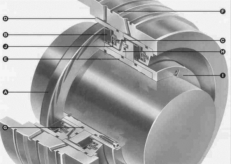
This type of seal is a cartridge design where all components are held within a meter retainer.  The stationary section of the seal comprises a spring loaded carbon primary ring with an O-ring sealing between the back face of the carbon primary ring and the metal sleeve.
The rotation section of the seal comprises a mating ring with grooves in the running face.  This ring is normally manufactured from tungsten carbide or silicon carbide.  The component is contained within a metal shroud and driven through drive lugs or flats machined on the outer diameter of the mating ring.  The O-ring sealed rotating seat is profiled with a series of spiral grooves having a depth of between 0.0023 to 0.010 mm as illustrated in the following Figure 2.
                                  
          
                   Figure-2
The design of the grooves is a logarithmic spiral.  The primary ring floats on a thin film of gas generated by the logarithmic spiral grooves (see Figure 3) in the surface of the mating ring.  As the mating ring rotates, this creates a hydrodynamic effect which, draws gas toward the root of the grooves and forces the two faces apart from the dynamic seal


                                                         Figure 3
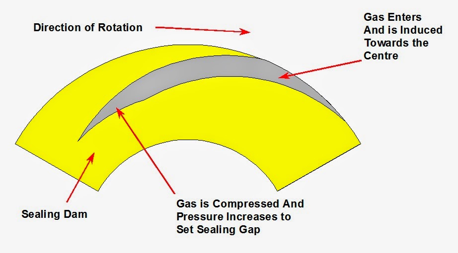
The principle of operation of the spiral groove gas seal is the balancing of aerostatic and aerodynamic forces to provide a stable, minimal running clearance.  When pressure is applied, the force exerted on the seal is aerostatic and is present both when the seal is stationary or rotating.  Aerodynamic forces are generated only upon rotation.  During rotation the spiral grooves play a vital role by generating a separating force which helps provide the means of achieving an acceptable sealing gap.  Figure 4 represents one of the spiral grooves.  The rotation of the seal scoops gas into the spiral grooves where it is induced toward the center until it meets the sealing dam.

                                                   Figure 4
This effect compresses the gas at the root of the grooves creating a pressure increase causing the flexibly mounted face to “lift off” thus establishing an operating clearance.  The size and number of grooves and the diameter of the sealing dam all contribute to the force balance of the seal.  Adjustment of which will determine whether “lift off” occurs under static pressure or at slow speed, a consideration necessary if the seal is to survive the crucial period of start up or shut down.


There is an optimum groove angle that, during operation, will generate maximum lift.  The constructor of the seals patents the optimized groove angle.  A radial slot will generate lift, but this may be insufficient to ensure that sealing gap is maintained at all times, thereby increasing the risk of contact particularly during transient conditions.
The pressure will also reduce when the groove angle is more acute.  A groove profile uses the key features of the optimized spiral to maximize lift and separation of the seal faces.  The optimized groove angle is also a critical design feature of the seal.

3       sealing interface

Under design conditions the forces acting upon the seal in operation can be graphically represented by those shown in Figure 5 producing an operating sealing gap of approximately 0.003mm.


                                         Figure 5
The closing force is a result of the system pressure acting behind the force plus a small force form the springs.  The opening force is a result of the system pressure plus the increase of force generated by the spiral groove.  Equilibrium in operation, with the designed sealing gap, is achieved when the opening force equals the closing force.
Whilst conditions remain steady and the forces remain in the same parallel relationship, the seal will continue to operate in the mode indicated. Should however there be some disturbances that results in a decrease in the sealing gap, the pressure generated by the spiral grooves considerably increases (see Figure 6).


                                                     Figure 6
Similarly should the upset cause the gap to increase, a reduction in the pressure generated by the grooves will occur (see Figure 7).  In each case, the closing force remains constant and so whichever situation is apparent, equilibrium is quickly established and the designed sealing gap restored.  This restoring mechanism is known as film stiffness.


                                                          Figure 7

This significant increase in film stiffness with small sealing gap changes ensures the seal becomes insensitive to pressure or mechanical disturbances, and there is no direct contact between the face and seal, regardless of system and mechanical upsets.
The spiral groove seal has both aerostatic and aerodynamic influences when in operation.  On rotation the aerostatic and aerdynamic effects are combined in the compression zone of the face, i.e. the area covered by the spiral grooves, whereas in the expansion zone across the sealing dam, the pressure distribution is governed only by the aerostatic effect.

4       Self aligning mechanism for radial film stability

Under ideal conditions the hard rotating ring should be perfectly flat and normal to the axis of rotation, in practice this is impossible to achieve.  There will always be some angular misalignment, whether from manufacturing tolerances or movements of the shaft in operation.
The mechanisms within the seal that produce such high levels of film stiffness compensate for these conditions and quickly re-establish equilibrium and film stability.
Ideally, there should always be a parallel presentation between the face and seat but in practice angular variations occur.  Generally, pressure deformations tend to close the faces at the outside diameter producing a different gap (see Figure 8).
The angular variation brings the outer half of the primary ring closer to the mating ring and the aerodynamic pressure generation rises.  As the gap widens in the inner half the pressure profile reduces.  The changes in pressure distribution between a parallel and a divergent film result in a returning moment, restoring parallel presentation to the operating gap.

                                     Figure 8
Thermal deformation tends to close the faces at the inside diameter producing a convergent gap (see Figure 9).  The resultant changes in pressure profile again combine to restore equilibrium.

                                   
   Figure 9

The net result of a high stiff fluid film is that the spiral groove seal can maintain a minimum running clearance without risk of face contact whilst compensating for a wide range of shaft displacements.

5       Arrangements

Different sealing arrangements can be formed with any of the seal types.  Selections for each arrangement are based on the type of gas, the equipment, the operating conditions and safety.  For non-hazardous gases where a small amount of leakage to the atmosphere does not present a problem, a single used.  An inboard labyrinth is usually includes in the arrangement to allow a small injection of clean gas to the seal environment, usually filtered gas from the compressor discharge (see Figure 10).


Figure-10                                                                                         

In cases where absolutely no process gas leakage to the atmosphere can be tolerated, a double face to face seal is used.  Buffer gas at a higher pressure than the sealed process gas is supplied between the sealing faces, thus ensuring that no process gas can leak to the atmosphere (see Figure 11).


                                           Figure 11

Tandem seal arrangements are a much-favored solution to most gas sealing problems and ideally suited for flammable, hazardous and low toxicity gases.  A tandem seal arrangement may have two or more seal modules oriented in the same direction behind each other (see Figure 12).


                                             Figure 12

The tandem arrangement may be used to share the sealing load or more commonly one seal handles the full system pressure while the outer seal runs as a standby or back-up seal while functioning as an additional barrier between the process gas and the atmosphere.  Very high pressures may require triple tandems for ultimate safety where the two inner seals share the sealing load, while the outer seal is a backup and barrier seal.
A variation of the tandem seal includes a labyrinth in the inter space between the seals (see Figure 13).  Utilized on more toxic applications, the intermediate labyrinth is purged with inert gas directing all the gas leakage to the primary vent, ultimately to be flared.


                                                       Figure 13


6       Control and Monitoring

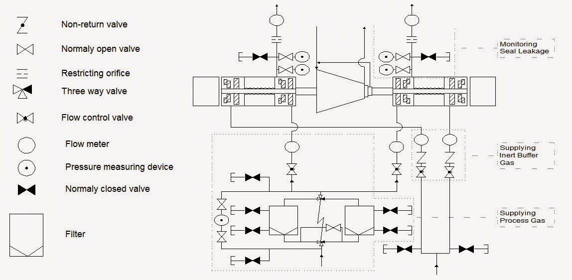
The dry gas seal does not require complicated ancillary equipment.  In most cases, all that is required is a simple control and monitoring system comprising filters, flow metering devices and pressure instrumentation.  The role of the control and monitoring system is to control the environment of the gas seal, monitor performance and initiate alarms or shutdown.  A single control system will usually supervise several seals in operation.
Figure 14 shows a typically flow diagram for a tandem seal with intermediate labyrinth.  Process gas is taken from the compressor discharge, cleaned through one of two filters and injected ahead of the seal cartridge.  The buffer gas is usually controlled at approximately ten times the seal leakage rate, thus ensuring that the seal environment remains clean.

                                                     Figure 14
A leakage outlet port is provided between the seals and piped via a pressure switch, flow restriction orifice and flow meter to a safe area.  A further leakage outlet port is provided on the atmospheric side of the seal, however, under normal conditions the outboard seal operates under very low differential pressure and thus leakage is minimal.  Continuous monitoring of seal leakage will immediately detect a malfunction in either the inboard or the outboard seals and initiate alarms while the process gas is still safety contained.
It is essential that the dry gas seal operates in a clean environment.  This is normally achieved by circulating the process gas from compressor discharge via one or two 5 micron filters and injected inboard of the seal cartridge at a rate of flow greater than the normal leakage rate of the inboard seal.  Flow of the filtered gas may be controlled either with a simple restricting orifice or flow control valve.
During static pressurization of the compressor, the filteration system is flooded with gas.  As soon as the compressor has developed a head of pressure at its discharge, the flow of process gas through the selected filter will commence.  A differential pressure gauge monitoring upstream and downstream pressures across the selected filter will determine filter condition.  A differential pressue high signal will alert the operator of the need to change the filter.
Leakage:
Gas seal integrity is confirmed by the systems leakage monitoring instrumentation (see Figure 15).  While statically pressurized, gas seal leakage is usually slight.  Under conditions of normal dynamic leakage, a flow will be registered in the primary vent.  A reduced primary leakage rate is indicative of an outboard seal malfunction.  An inboard seal malfunction will cause an increase in primary leakage.  A flow meter with high and low leakage alarm signal will give the operator warning of the malfunction.


                                                             Figure 15
Should a serious breach of the inboard seal occur, a restricting orifice would restrict leakage through the primary vent.  A trip signal is generated by the pressure increase upstream of the orifice.
Buffer Gas:
Tandem seals with intermediate labyrinth are often purged with an inert gas.  This ensures that process gas leakage from the inboard gas seal is directed to the primary vent.  The outboard seal operates on the inert gas and process gas is prevented from entering the bearing area of the compressor inert gas flow is controlled by a simple control valve and monitored by a flow meter.  A low flow alarm provided warning of inert gas header failure.

7       key operational consideration

Experience has shown that the majority of seal malfunctions are caused by contamination of the seals by solids and liquids.  It is particularly important for reliable operation to keep the dry gas seal clean and dry.  This can be normally achieved by circulating the warm gas from compressor discharge via the filter to the seal chamber.
Dirty Gas:
In some instances, the process gas may be considered particularly dirty and during periods of standstill there may be a risk of the dirty gas entering the seal cavity.  In such cases, it may be appropriate to utilize a clean buffer gas.  This must be compatible with the process gas and be available at a pressure higher than system pressure.  The buffer gas is circulated to the seal chamber via the filter gas supply system.
Gas Condensate Liquids:
Condensing of the compressed gas occurs mainly when there are significant quantities of heavy hydrocarbons present.  They will condensate out when the temperature is below the dew point of the gas.  Gas condensate liquid can present themselves as an oily, sticky substance.  When present in the seal area, this can coat all seal components.
The liquid will congeal and clog, preventing free movement of the seal components.
Condensing of the compressor gas is most likely to occur:
·         When the filtered gas stream pressure reduces through a throttling device such as a restriction orifice or pressure regulator.  As the gas expands the “Joule Thomson” effect causes it to cool and the heavy hydrocarbons condense out as liquid.
·         As a result of cooling when the compressor is circulated through pipework from compressor discharge via filters to the seal area
·         During static settle-out conditions when the compressor casing is pressurized and the temperature drops below the dew point of the gas.
Small quantities of condensate can be tolerated by the dry gas seal due to the heating effect of the small gap.  The seal generates a small temperature rise (typically 20 C) which is normally sufficient to “boil away” condensate.  For applications involving substantial amounts of heavy hydrocarbons, various solutions to prevent the formation of gas condensate liquid include the following:
·         Maintain the temperature above the dew point of the compressor gas.  Heat trace filters gas pipework if necessary or source clean gas supply horn a warmer area.
·         Keep length of filter gas pipework between compressor discharge and seal chamber to a minimum.  Lag pipework to reduce heat loss.
·         Minimize pressure differential across throttling device I filter gas line, which will limit the cooling effect of the gas.  Consider receiving the compressed gas from an intermediate stage of the compressor.
·         Install coalescing filters in the filter gas line, preferably downstream of the throttling device to maximize removal of condensate.  This may result in a requirement for large filter size due to a resuction in the filter capacity at lower pressure.
·         Control the seal environment b circulating a filtered dry external buffer gas to the inboard dry gas seal.
·         Avoid or minimize duration seals are subjected to high-pressure settle out condition.
·         Install a double seal design with a pressurized nitrogen barrier gas between the seals.
Avoidance of gas condensate liquids may require any one or a combination of the above solutions dependent on risk or severity.  A full analysis of the process gas should be made to assess the potential for liquids to condense out.
Sour Gas:
The application of dry gas seals to sour gases has been extensive many of the natural gas applications in offshore environments and hydrocarbon rich applications on refineries include quantities of hydrogen sulphide of sulphur.
Critical considerations are material selection, leakage hazards and environmental limitations.  Materials are selected in compliance with NACE specification MR0175-96 which specifies acceptable materials, the requisite heat treatment and the maximum permitted hardness, for avoidance of sulphide stress cracking.
Generally, for natural gas and hydrocarbon recycle applications, tandem seals are preferred.  To prevent sour gas leakage to the secondary vent an intermediate labyrinth may be installed between the seals and purged with nitrogen to ensure that under normal operating conditions sour gas leakage through the inboard seal is directed to the primary vent to be flared.
In extremely sour gas application, it is normally required that the compressor gas is fully contained with no venting to atmosphere.  In such cases, a double seal design is selected with a pressurized nitrogen barrier gas between the seals.
Hydrate and ice formation:
Under certain conditions hydrates may form in hydrocarbon gases.  This occurs when molecules of water attach elements of the hydrocarbon gas to form crystals.  The conditions promoting hydrate formation are shown as follows:
·         Gas is at or below its water dew point with “free” water present
·         Low temperature
·         High pressure
Secondary considerations include:
·         High gas velocities
·         Pressure pulsations
·         Any type of agitation
·         Introduction of hydrate crystals
Cold ambient shutdown conditions are those more likely to cause hydrate formation in the gas seal cartridge, when the inboard seal is pressurized to compressor casing settle-out pressure.
There is also potential for icing if there is a release of water from the gas during high-pressure cold ambient shutdown conditions.  As the gas containing the “free” water or vapor expands across the inboard seal faces, the Joule Thomson expansion cooling can potentially form ice.
Application where there is a risk if ice or hydrate formation during prolonged periods of pressurized shutdown should incorporate a purge of the gas seal interspace with “warm” buffer gas flow prior to compressor start-up or some method of gas seal cartridge warm through.
Wet chlorides:
Wet chloride is an aggressive contaminant.  Material distress takes the form of pitting and stress corrosion cracking.  Tungsten carbide and stainless steels can degrade in the presence of wet chloride contamination so alternative materials such as duplex  stainless steel, hastelloy and silicone carbide are normally selected.
It can be seen that where gas conditions exceed the design criteria of the seal (as in very dirt gases) the seal environment is adjusted to assure long and trouble free life.

8       Benefits of dry gas seals

The spiral groove gas seal offers several benefits over conventional oil lubricated seals:
·         Low pressure consumption
·         No wear in operation
·         No seal oil system required
·         No pressure/velocity limit
Low power consumption:
The parasitic power consumption of a sealing device is very often a hidden cost that is not fully appreciated.  To make a comparison between a conventional seal and a spiral groove gas seal, consider a 125 mm liquid lubricated mechanical contact seal handling gas at 50 bar, 10000 rpm, the power absorbed would be 20 to 25 kW.  Dry lubricated seals offer virtually no resistance reducing frictional losses by up to 98 percent, leading to significant power saving.
No wear in operation:
The spiral groove gas seal is non-contacting; hence there are no wearing parts.  While the shaft is rotating, a thin film of gas separates the seal surface.  Therefore seal wear is avoided.


No seal oil system required:
In dry gas seals, the sometimes complex and heavy oil systems are replaced by a clean and compact control and monitoring system.  An oil system must contain a reservoir, pumps, coolers, filters, pipe work, separators and controls, some of which must be duplicated for overall separators and controls, some of which must be duplicated for overall integrity.  The spiral groove gas seal avoids this complication.  It requires a simple gas backup system and can be procured and installed at lower costs.  The dry gas seal system cuts maintenance and removes the need for lubricating oil.  As a result, contamination of the process gas is effectively eliminated.  Elimination of the wet seal gas seal system operational safety by eradicating any dangerous builds up of hydrocarbon gas in the seal oil.
No pressure/velocity limit:
Although a general speed limit of 100 m/s has been imposed on the gas seal, the ultimate speed that can be achieved is limited by the material strength.  In the case of liquid with higher power consumption and hence higher interface temperatures, the limit is not only one of strength but also the ability to conduct heat the spiral groove gas seal is independent of any pressure/velocity limit.
Improved rotor stability:
Traditional oil ring seals can be unpredictable to excitement of the shaft and rotor stability.  Dry gas seal are very predictable and will not effect rotor stability.

9       Cause and effect on dry gas seals

Cause: lack of buffer gas while the tube oil pump is running
Effects:
·         The lube oil can migrate from the oil separation seal via the compressor shaft toward the DGS
·         This oil will fill up the clearance volume in secondary leakage and slowly penetrate through DGS
·         The stator ring and the rotor ring of DGS will stick together and will not lift off while the compressor is rotating
·         The rotor ring of the DGS will burst immediately

Cause: compressor casing pressurized during long period of standstill
Effect:
·         In that case, no clean gas will be supplied via the clean gas filters to the DGS from the process side
·         A small leakage rate through the seals in always present.  As there is no clean gas supplied to the seal for protection, dirt from process side can migrate through the seals.
·         When the compressor rotor is started, this dirt can cause damage to the rotor ring as well as to the stator ring.

Cause: no maintenance on the clean gas filters
Effects:
·         In case of excessively high differential pressure on the filters, only a small amount of clean gas can be supplied to the DGS for protection.  This amount will be smaller than the normal leakage rate for the DGS.
·         Due to this effect, a small amount of dirty process gas will migrate through the seals, and this will act like sand blasting.
·         Over a long period of compressor operation, an increasing leakage rate on the primary leakage can be recognized.

Cause: wet process gas
Effects:
·         The volatile constituents of the leaking process gas will disappear through the primary leakage of DGS, while crystals will be precipitated out of the process gas (knocked out).  This process precipitation will be enforced by the temperature loss of the process gas expanding through the seals and labyrinth.
·         Crystal will block the installed springs and labyrinth.  To protect the seal from wet and dirty gas, the clean gas system can be adapted with trace heating as well as with knockout containers installed in the line behind the normal clean gas filters.

DC Testing Methods

$
0
0
After seeing how insulation behaves when DC voltage is applied to it, let us now take a look at the various tests that are conducted with this voltage. Two tests can be conducted on solid insulation with the application of DC voltage:

• Insulation resistance testing
• High-potential (Hi-pot) voltage testing


 Insulation Resistance Testing

This test may be conducted at applied voltages of 100–15,000 V. The instrument used is a megohmmeter, either hand cranked, motor driven, or electronic, which indicates the insulation resistance in megohms. An electronic megohmmeter is shown in Figure 1.1. The quality of insulation is a variable, dependent upon temperature, humidity, and other environmental factors.
Therefore, all readings must be corrected to the standard temperature for the class of equipment under test. The megohm value of insulation resistance is inversely proportional to the volume of insulation being tested. As an example, a cable 100 ft. long would have one-tenth the insulation resistance of cable 1000 ft. long, provided other conditions were identical. This test can be useful in giving an indication of deteriorating trends in the insulation system. The insulation resistance values by themselves neither indicate the weakness of the insulation nor its total dielectric strength. However, they can indicate the contamination of the insulation and trouble ahead within the insulation system if a downward trend continued in the insulation resistance values.


FIGURE 1.1
(a) Electronic megohmmeter, 5000 V and (b) 15 kV DC dielectric test set. (Courtesy of Megger, Inc., Valley Forge, PA.)


Insulation resistance measurement values can be accomplished by four
common test methods:
• Short-time readings
• Time-resistance readings (dielectric absorption ratio [DAR] test)
• Polarization index (PI) test
• Step-voltage readings  


High-Potential Voltage Test 

A DC hi-pot voltage test is a voltage applied across the insulation at or above the DC equivalent of the 60 Hz operating crest voltage (i.e., DC value = 1.41 times RMS value). This test can be applied as a step-voltage test. When the highpotential voltage is applied as a dielectric absorption test, the maximum voltage is applied gradually over a period of 60–90 s. The maximum voltage is then held for 5 min with leakage current readings taken each minute. When this test is applied as a step-voltage test, the maximum voltage is applied in a number of equal increments, usually not less than eight, with each voltage step being held for an equal interval of time. The time interval between each step should be 1–4 min. At the end of each interval, a leakage current or insulation resistance reading is taken before proceeding to the next step. A plot of test voltage versus leakage current or insulation resistance can then be drawn to indicate the condition of the insulation system. Routine maintenance tests are conducted with a maximum voltage at or below 75% of the maximum test voltage permitted for acceptance tests, or at 60% of the factory test voltage. 

Dielectric absorption test: The dielectric absorption test is conducted at voltages much higher than the usual insulation resistance test values and can exceed 100 kV. This test is an extension of the hi-pot test. Under this test, the voltage is applied for an extended period of time, from 5 to 15 min. Periodic readings are taken of the insulation resistance or leakage current. The test is evaluated on the basis of insulation resistance. If insulation is in good condition, the apparent insulation resistance will increase as the test progresses.
The dielectric absorption tests are independent of the volume and the temperature of the insulation under test.

Transformers Insulation Resistance Measurement

$
0
0

This test is performed at or above rated voltage to determine if there are low resistance paths to ground or between winding to winding as a result of winding insulation deterioration. The test measurement values are affected by variables such as temperature, humidity, test voltage, and size of transformer.
This test should be conducted before and after repair or when maintenance is performed. The test data should be recorded for future comparative purposes. The test values should be normalized to 20°C for comparison purposes. The general rule of thumb that is used for acceptable values for safe energization is 1 MΩ per 1000 V of applied test voltage plus 1 MΩ. Sample resistance values of good insulation systems are shown in Table. The test procedures are as follows:


Typical Insulation Resistance Values for Power and Distribution Transformers


1. Do not disconnect the ground connection to the transformer tank and core. Make sure that the transformer tank and core are grounded.
2. Disconnect all high-voltage, low-voltage, and neutral connections, lightning arresters, fan systems, meters, or any low-voltage control systems that are connected to the transformer winding.
3. Before beginning the test, jumper together all high-voltage bushings, making sure that the jumpers are clear of all metal and grounded parts. Also jumper together all low-voltage and neutral bushings, making sure jumpers are clear of all metal and grounded parts.
4. Use a megohmmeter with a minimum scale of 20,000 MΩ.
5. Resistance measurements are then made between each set of windings and ground. The windings that are to be measured must have its ground removed in order to measure its insulation resistance.
6. Megohmmeter reading should be maintained for a period of 1 min.
Make the following readings for two-winding transformers:
a. High-voltage winding to low-voltage winding and to ground
b. High-voltage winding to ground
c. Low-voltage winding to high-voltage winding and to ground
d. Low-voltage winding to ground
e. High-voltage winding to low-voltage winding


The connections for these tests are shown in Figures 1.1a through e and 1.2a through e for single-phase and three-phase transformers, respectively.


Megohmmeter readings should be recorded along with the test temperature (°C). The readings should be corrected to 20°C by the correction factors shown in Table. If the corrected fi eld test values are one-half or more of the factory insulation readings or 1000 MΩ, whichever is less, the transformer insulation system is considered safe for a hi-pot test.


Figure 1.1 Test connections for insulation resistance of a single-phase transformer. Note: In figure (e) reverse the L and E leads to measure from high-winding to low-winding. 

For three-winding transformers, test should be made as follows:
High to low, tertiary and ground (H-LTG)
• Tertiary to high, low and ground (T-HLG)
• Low to high, tertiary and ground (L-HTG)
• High, low, and tertiary to ground (HLT-G)
• High and tertiary to low and ground (HT-LG)
• Low and tertiary to high and ground (LT-HG)
• High and low to tertiary and ground (HL-TG)


Do not make the megohm test of the transformer winding without the transformer iquid because the values of insulation resistance in air will be much less than in the liquid. Also, do not make the insulation resistance test of the transformer when it is under vacuum because of the possibility of  flashover to ground.
The test connections shown in Figure 1.1a, c, and e are most frequently used. The test connections in Figure 1.1b and d give more precise results.
The readings obtained in the connections in Figure 1.1a and b are practically equal to readings in test connections in Figure 1.1c and d, respectively.


DC voltage testing of electrical equipment


FIGURE 1.2
Test connections for insulation resistance of a three-phase transformer: (a) connection for high winding to low winding to ground; (b) connection for high winding to ground and low winding guarded; (c) connection for low winding to high winding to ground; (d) connection for low winding to ground and high winding guarded; and (e) connection for high winding to low winding.

Acceptable insulation resistance values for dry and compound-filled transformers should be comparable to those for Class A rotating machinery, although no standard minimum values are available.
Oil-filled transformers or voltage regulators present a special problem in that the condition of the oil has a marked influence on the insulation resistance of the windings.
In the absence of more reliable data the following formula is suggested:

where
IR is the minimum 1 min 500 V DC insulation resistance in megohms from winding to ground, with other winding or windings guarded, or from winding to winding with core guarded
C is a constant for 20°C measurements
E is the voltage rating of winding under test
kVA is the rated capacity of winding under test


This formula is intended for single-phase transformers. If the transformers under test is one of the three-phase type, and the three individual windings are being tested as one, then E is the voltage rating of one of the single-phase windings (phase to phase for delta connected units and phase to neutral or star connected units) kVA is the rated capacity of the completed three-phase winding under test.

Alstom Frame 5 Turbine Assembling Photos

$
0
0
 1st stage nozzle clamp right side
 1st stage nozzle clamp
 1st stage nozzle complete
 1st stage nozzles installed
 accessory coupling
 accessory coupling complete
 1st stage shrouds and 2nd stage nozzles installed
 1st stage nozzles installed
 all pipes installed
 all pipes installed
 all transition pieces in machine
 assembling accessary coupling tunnel
 assembling pipes (2)
 assembling first st. shrouds and second st. nozzles
 assembling exhaust plenum
 assembling exhaust plenum
 assembling pipes
 assembling second stage nozzles
 bad welding exhaust
 bad welding
 bearing nr.1
 bearing no. 2 installed
 bearing no.1 complete
 bellmpouth installed
 bellmpouth installed

 bottom of 1st stage nozzle with pin
 broken bolt in support ring
 cleaned coupling of rotor
 cleaned and repainted bellmouth
 cleaned and repainted bellmouth
 broken cable piping
 cleaning rotor for assembling 1
 cleaning rotor for assembling buckets
 closing bearing no.2
 closing bearing no.2
 compleet bearing nr.1
 combustion chambers installed
 combustion chambers installed
 combustion chamber covers installed
compleet bearing nr.1

DC High-Potential Test

$
0
0

The DC hi-pot test is applied at above the rated voltage of a transformer to evaluate the condition of winding insulation. The DC high-voltage test is not recommended on power transformers above 34.5 kV; instead the AC hi-pot test should be used. 

Generally, for routine maintenance of transformers, this test is not employed because of the possibility of damage to the winding insulation. However, this test is made for acceptance and after repair of transformers.
If the hi-pot test is to be conducted for routine maintenance, the AC test values should not exceed 65% of factory AC test value. The routine maintenance AC voltage value should be converted to an equivalent DC voltage value by multiplying it by 1.6, that is, 1.6 times the AC value for periodic testing (i.e., 1.6 × 65 = 104% of AC factory test value). The DC hi-pot test can be applied as a step-voltage test where readings of leakage current are taken for each step. If excessive leakage current is noticed, voltage can be backed off before further damage takes place. For this reason, the DC hi-pot test is considered to be a nondestructive test.

 Some companies conduct the AC hi-pot test at rated voltage for 3 min for periodic testing instead of the 65% of factory test voltage. The hi-pot test values for DC voltages are shown in Table 1.1.
The procedure for conducting this test is as follows (refer to Figure 1.1a and b for test connections):


FIGURE 1.1
Transformer high voltage (hi-pot) test connection: (a) high winding hi-pot test connection and
(b) low winding hi-pot test connections. 


Transformer must have passed the insulation resistance test immediately
prior to starting this test.
• Make sure transformer case and core are grounded.
• Disconnect all high-voltage, low-voltage, and neutral connections,
low-voltage control systems, fan systems, and meters connected to the transformer winding and core.
• Short-circuit with jumpers together all high-voltage bushings and all low-voltage bushings to ground as discussed under “Insulation resistance measurements.


Connect hi-pot test set between high-voltage winding and ground.
Gradually increase test voltage to the desired value. Allow test voltage duration of 1 min, after which gradually decrease voltage to zero.
• Remove low-voltage to ground jumper and connect hi-pot test set
between low-voltage winding and ground. Also connect the shortcircuited
high-voltage winding to ground. Gradually increase test voltage to desired value. Allow the test voltage duration of 1 min, after which gradually decrease voltage to zero.
• If the preceding two tests do not produce breakdowns or failures, the transformer is considered satisfactory and can be energized.
• Remove all jumpers and reconnect primary and secondary connections and other system equipment that may have been disconnected.
The following are some cautions and considerations in performing hi-pot
tests:
In liquid-filled transformers two insulation systems are in series, that is, solid insulation with oil or synthetic fluid. When AC or DC hi-pot test voltage is applied, the voltage drops are distributed as follows:


 Table 1.1
 

When using DC hi-pot test voltage on liquid-filled transformers, the solid insulation may be overstressed.
Insulation that may be weakened near the neutral may remain in service due to lower stress under operating conditions. However, when subjected to hi-pot test voltage, it may break down and require immediate repair. The weakened insulation may usually be detected by the measurement at lower voltages.
If a hi-pot test is to be conducted for routine maintenance, consider the following in advance: (1) assume that a breakdown will occur, (2) have replacement or parts on hand, (3) have personnel available to perform work, and (4) is the loss of the transformer until repairs are made beyond the original routine outage.


Electrical Cables and Accessories Testing 1

$
0
0

Cable testing is conducted to chart the gradual deterioration over the years, to do acceptance testing after installation, for 
verification of splices and joints, and for special repair testing. Normally, the maintenance proof tests performed on cables are at a test voltage of 60% of final factory test voltage.
When the exact construction of cable in an existing installation is not known, it is generally recommended that DC maintenance proof test voltage be based on rated AC circuit voltage using the recommended value for the smallest sized conductor in the rated AC voltage range. The DC voltage tests conducted on cable are insulation resistance measurement and DC hi-pot test.
The DC hi-pot test can be performed as leakage current versus voltage test, leakage current versus time test, or go, no-go overpotential test.
It is always appropriate to conduct the insulation resistance measurement test first, and if data obtained looks good, then proceed with the DC overpotential test. After DC overpotential test is completed, then perform the insulation resistance again to assure that the cable has not been damaged during the DC overpotential test.

Insulation Resistance Measurement Test

The insulation resistance is measured using a Megohmmeter (or it can be measured using a portable instrument consisting of a direct voltage source, such as a generator, battery, or rectifi er, and a high-range ohmmeter that gives insulation resistance readings in megohms or ohms). This is a nondestructive method of determining the condition of the cable insulation to check contamination due to moisture, dirt, or carbonization. The insulation resistance measurement method does not give the measure of total dielectric
strength of cable insulation or weak spots in the cable. Generally, the following voltages can be used for the indicated cable voltage rating.

The following is the general procedure when using a megohmmeter (Megger)*
for resistance measurement tests.
Disconnect the cable to be tested from other equipment and circuits
to ensure that it is not energized.
• Discharge all stored capacitance in the cable by grounding it before testing, as well as after completing tests.
• Connect the line terminal of the instrument to the conductor to be
tested.
• Ground all other conductors together to sheath and to ground.
Connect these to the earth terminal of the test set.
• Similarly measure other insulation resistance values between one conductor and all other conductors connected, one conductor to ground and so on. The connections are shown in Figure 1.1a through d.
• The guard terminal of the megohmmeter can be used to eliminate
the effects of surface leakage across exposed insulation at the test
end of the cable, or both ends of the cable for leakage to ground.

The insulation resistance measurements should be conducted at regular intervals and records kept for comparison purposes. Keep in mind that, for valid comparison, the readings must be corrected to a base temperature, such as 20°C. A continued downward trend is an indication of insulation deterioration even though the resistance values measured are above the minimum
acceptable limit.

Cable and conductor installations present a wide variation of conditions from the point of view of the resistance of the insulation. These conditions result from the many kinds of insulating materials used, the voltage rating or insulation thickness, and the length of the circuit involved in the measurement. Furthermore, such circuits usually extend over great distances, and may be subjected to wide variations in temperature, which will have an effect on the insulation resistance values obtained. The terminals of cables and conductors will also have an effect on the test values unless they are clean and dry, or guarded.


Figure 1.1
Cable test connections for insulation resistance measurement: (a) connection for single-conductor cable, one conductor to ground test; (b) connection for three-conductor cable, one conductor to other conductors and sheath to ground; (c) connection for three-conductor cable, one conductor to sheath and to ground and two conductors guarded; and (d) connection for three-conductor cable, one conductor to all other conductors without leakage to ground.

The Insulated Cable Engineers Association (ICEA) gives minimum values of insulation resistance in its specifi cations for various types of cables and conductors. These minimum values are for new, single-conductor wire and cable after being subjected to an AC high voltage test and based on a DC test potential of 500 V applied for 1 min at a temperature of 60°F.
These standard minimum insulation resistance (IR) values (for single conductor cable) are based on the following formula:

where
IR is in megohms per 1000 ft of cable
K is a constant for insulating material
D is the outside diameter of conductor insulation 
d is the inside diameter of conductor
 
The insulation resistance of one conductor of a multiconductor cable to all others and sheath is


where
D is the diameter over insulation of equivalent single-conductor cable =
d + 2c + 2b
d is the diameter of conductor (for sector cables, d equals diameter of round conductor of same cross section)
c is the thickness of conductor insulation
b is the thickness of jacket insulation
 
Also, the IEEE standard 690-1984* and 422-1986† recommended an insulation resistance field acceptance limit of  where
L is the cable length in feet
kV is the insulation voltage rating

Electrical Cables and Accessories Testing 2

$
0
0
DC Overpotential Testing
 
In the past, this test has been extensively used for acceptance and
maintenance of cables. Recent studies of cable failures indicate that the DC overpotential test may be causing more damage to some cable insulation, such as cross-link polyethylene, than the benefit obtained from such testing. It can indicate the relative condition of the insulation at voltages above or near operating levels. This test can be used for identifi cation of weakness in the cable insulation and can also be used to break down an incipient fault. A typical DC test set is shown in Figure 1.1. Generally, it is not recommended that this test be used for breakdown of incipient faults even though some test engineers use it for this purpose. Therefore, the incipient fault breakdown probability should be anticipated before and during the hi-pot test. The impending cable failure will usually be indicated by sudden changes in the leakage current, and before insulation is damaged, the test can be stopped. The test voltage values for DC hi-pot tests are based upon fi nal factory test voltage, which is determined by the type and thickness of insulation, the size of conductors, the construction of cable, and applicable industry standards. The DC test values corresponding to AC factory proof test voltages specified by the industry standards are usually expressed in terms of the ratio of DC to AC voltage for each insulation system. This ratio is designated as K, which when multiplied by the acceptance test factor of 80% and maintenance factor of 60% yields the conversion factors to obtain the DC test voltages for hi-pot tests. These recommended test voltage conversion factors are shown in Table 1.1. Also, the IEEE standard 400.1–2007 lists the voltage values for conducting hi-pot acceptance and maintenance tests in the field for laminated shielded power cables, which are shown in Table 1.2.


Many factors should be considered in selecting the right voltage for existing cables that are in service. As a general rule, for existing cables, the highest values for maintenance should not exceed 60% of final factory test voltage,


Figure 1.1 
DC hi-pot test set, 70 kV. (Courtesy of Megger, Inc., Valley Forge, PA.) 

and the minimum test value should be not less than the DC equivalent of the AC operating voltage. If the cable cannot be disconnected from all the connected equipment, the test voltage should be reduced to the voltage level of the lowest rated equipment connected. The hi-pot test can be conducted as a step-voltage test as discussed next.

Table 1.1 Conversion Factors for DC Hi-Pot Tests


 Table 1.2
Field Test Voltages for Laminated Shielded Cables up to 69 kV System Voltage

  
Note: Voltages higher those listed, up to 80% of system BIL for installation and maintenance testing may be considered in consultation with the suppliers of cable and the accessories.
When equipment, such as transformers, motors, etc., is connected to the cable circuit undergoing a test, voltages lower than recommended values may be used to comply with the limitations imposed by the connected equipment. a Maintained for a duration of 15 min.

Basic Seal Oil Systems

$
0
0
OPERATION / SYSTEM DESCRIPTION:
 
The purpose of the seal oil system is to keep the compressed gas from entering the bearing assembly and escaping from the compressor to the atmosphere. The seal oil system may be a completely separate oil system, however in most cases it is apart of the compressor (main) lube oil system. The seal oil system can be considered as having three major levels of operation: Seals, Oil Supply, and Oil Return.


SEAL OIL SUPPLY SYSTEM:

The oil supply consists of a reservoir, pumps, filters, pressure control valve, cooler, level control valve and overhead tanks.


Typical Seal Oil Supply System

The oil used is held in an tank, which is purged to clear the tank of any gas at 3" w.c. vacuum by a jet blower attached to the reservoir. Also attached to the reservoir are two electric motor driven pumps that are selectable to run from the UCP (unit control panel), however, only onepump should be selected to run at any one time.

 Now all that is needed is to control oil pressure to the seal. It is known that a greater oil pressure must be supplied to the seal than the gas pressure against the seal. So an overhead tank has been added to accomplish this task. The overhead tank is supplied with oil from the oil supply cavity of the oil film seal through the seal oil by-pass piping and with reference gas pressure piped to the top of the tank from the outboard side of the thrust balance piston.
 
In order to fill the tank with oil, the oil pressure must be greater than the gas pressure. By mounting the tank above the compressor, the oil supply pressure to the seals must then be even greater to overcome the added gravitational force of oil in the by-pass line and tank.
To summarize, the supply of seal oil should be equal to the gas reference pressure plus the head of oil maintained in the overhead tank serving each set of seals in each compressor. Seal differential is the head of oil maintained in the tank against the seal.
 
  
COMPONENT DESCRIPTION:
Seals:
Cooper-BessemerÒ Compressors use the labyrinth and oil film type seals working in combination within a cartridge to seal against gas leakage during operation whenever gas is present in the compressor. Each end of the compressor is equipped with a seal cartridge.

Cutaway of a typical Barrel Compressor

Typical Labyrinth Seal

LABYRINTH SEAL:

A labyrinth seal has a series of teeth with a close clearance to the shaft (See above illustration). Labyrinth seal work similar to an orifice in a pipe.

As the high pressure gas passes through the first tooth the pressure is decreased to approximately half its original pressure and velocity is increased. The gas then enters the chamber before the second tooth. A natural turbulence is created, which reduces the velocity allowing the gas to expand in the cavity between labyrinth teeth. This process is repeated for each tooth of the labyrinth. The result is a large reduction in gas pressure across the seal.

OIL FILM SEAL CARTRIDGE:

The oil film seal is made up of two free floating rings which are machined with a very small clearance around the shaft (See following illustration). Clean high pressure oil is squeezed between the rings and shaft, and out both directions. As long as the oil pressure is greater then the gas pressure, the seal will not allow gas to escape.


Typical Oil Film Seal 
 
The seals are bench assembled as a cartridge. The seal cartridge is put onto the shaft and in to the compressor at each end. Because the oil film seal requires an oil supply and drainage, the casing and cartridge housing are machined and drilled with matching annular ports, or, holes (See above illustration). These annular ports are sealed from one another by Orings assembled onto the O.D. of the cartridge. 

SEAL OIL Cartridge SUPPLY:

Seal oil is supplied and flows between the seal rings (See following
illustration). The majority of oil will flow to the low pressure side of the seal cartridge. The high pressure side of the seal cartridge is where the gas and oil come into contact with one another. The labyrinth seal on the high pressure side of the seal cartridge reduces the higher gas pressure. This reduced gas pressure is sealed from the system by the high pressure oil passing through the gas side seal ring. Oil supply is maintained at a greater pressure between the seal rings than compressor suction pressure to insure a positive seal and safe operation at all times. 


Typical Seal Oil Supply Flow


SEAL OIL RETURN:

SEAL OIL CARTRIDGE RETURN OIL FLOW:

 
The oil flowing to the bearing side (low pressure) of the seal cartridge is not contaminated with gas, and returns directly to the reservoir. The oil flowing to the process side (high pressure) of the seal cartridge is contaminated with gas and goes to the degasser system.
 
The return of oil from each seal is provided by two ports off the
compressor housing. A 1-1/2" pipe is connected to the outboard side of the oil film seal. This uncontaminated oil is returned to the reservoir. This is where the majority of oil will flow. On the inboard side of the oil film seal, the oil comes in contact with a small amount of gas that has leaked past the labyrinth seal. This contaminated oil must be treated specially before returning it to the reservoir. 

The first step of this treatment is the trap system. The oil is sent from the compressor to the trap through a 1" pipe.
Provided the pressure in the pipe is over 5 psig, it will enter the trap. If less than 5 psig, it will pass through an excessive flow valve and directly to the degasser tank for gas removal. The excessive flow valve is used to keep the seal from flooding when the compressor case is not pressurized.

Trap System

The trap is a vessel that is level controlled and ported at the top for gas venting and bottom for oil drainage. The oil enters the trap and is given some time to allow the gas to separate from the oil, until the level of oil becomes too high and is drained.

 This process is controlled by a level controller that regulates 100 psig air supply to a 3-15 psig control signal. This control signal is sent to a dump valve that is adjusted to open at 12 psig and to a high trap level alarm switch. The oil drains through the dump valve and into a common pipe with the other trap drains to the degasser system. The vented gases from the traps are passed through a final demister before going to atmosphere.

DEGASSER TANK:

The degasser tank is the second stage of removing gas from the oil. It is a tank with baffles of various heights. The contaminated oil enters into the first chamber and is heated. This heating thins the oil and allows the gas to separate faster and easier. The element used for heating the oil is controlled through the Motor Control Center (MCC), which will control the temperature using an adjustable temperature switch. The temperature is also monitored by the UCP that will generate an alarm for low or high temperatures. Should the oil level in this chamber drop below 12 inches, a level switch will disconnect the power to the heater. The oil will pass over the other baffles that will agitate the oil and release all the gas. The final chamber oil level will be monitored by a level switch that will generate a low level alarm at the UCP. Once in the final chamber, the oil will be drained back to the reservoir for re-use. 

The degasser tank also requires a purge of gas that is supplied off the suction header through a separator and filter. This purging gas keeps the gas content in the tank at a high
enough level so it is not explosive. The purge gas supply is controlled and monitored by the UCP through a solenoid and pressure switch.

BALANCING:

SEAL BALANCING:

The gas pressure in on the inboard side of the seal cartridges is equalized by an interconnecting pipe called the seal balance line. This allows for one seal system to supply both end seals during operation rather than two separate systems, one serving each seal. 

A gas reference line is piped from the thrust balance port on the discharge end of the compressor to a supply of seal oil maintained in an overhead tank approximately 5-6 meters above the horizontal centerline of each compressor. While the unit is running and the compressor case is pressurized, the reference gas represents the pressure used to seal against.

Typical Seal Balance Piping

THRUST BALANCE:

Suction gas pressure is piped from the suction of the compressor to a port behind the thrust balance piston by the thrust balance piping. The thrust balance line is used in conjunction with the thrust balance piston and labyrinth to reduce excessive forces of the thrust toward suction that develops during normal operation. The gas pressure behind the thrust balance piston will be suction pressure plus a small amount of gas leakage across the balance piston from the last stage impeller. Under any circumstances, the pressure behind the thrust balance piston represents the pressure necessary to seal against.
Typical Thrust Balance Piping
OPERATION:

Should one of the pumps fail during operation, A pressure switch would operate and show a seal oil supply low alarm and start the other pump. Should the filter become plugged, a differential pressure switch will send a signal to the UCP and an alarm will be sounded. The filter should be selected to the spare and the dirty one cleaned or replaced.

Now that the tank is elevated and has this added gas pressure, the oil within the tank will supply emergency oil to the seals for a period of time should the pumps shut off. Now what is needed during operation is a controller to maintain the correct oil level in the overhead tank. This is done by a Fisher pneumatic level controller that will regulate a 100 psig air supply to 3-15 psig depending on the level in the tank. This signal is then connected to a controller valve that will regulate the oil pressure going to seals. The controller must be set to maintain the recommended level in the overhead tank serving each compressor. This is done by loosening the spring to fill the tank higher or tightening the spring for a lower level. There is also added a main regulating valve which may be adjusted by tightening the spring to raise the levels of both tanks or loosening to decrease levels.

Startup of the Coberra Gas Turbine Unit is initiated by startup of the electric motor driving selected L.O. pump to deliver oil to the compressor overhead seal oil rundown tank via the seal boost pump, this fills the system and ensures proper supply of oil to the machinery. During this phase of startup, the lube oil rundown tank serving the disc end journal bearing on an emergency shutdown involving loss of power, is also filled.

Establishing correct L.O. pressure as well as seal and lube oil tank levels
is required for the startup control sequence to progress. The supply must be sufficient to ensure against the escape of any gas within the compressor, maintaining a positive sealing of the gas within the casing during operation or shutdown if the cases remained pressurized.
 
During normal operation only one of the seal oil pumps is on-line.  The other pump, depending upon selection, functions as a back-up pump should alarms occur.
Once the system has been proven during start the following will occur:

1. Arm the Lube and Seal Oil Low & High Level and Pressure alarm and shutdowns in the system.

2. The Unit is ready for further sequencing as follows:

· System ready for compressor case purge and pressurization cycles

· Unit valve sequencing can begin.

· When purging and pressurizing of the compressor case is
completed and valves are in correct position it is they permissible to start the gas generator.


Voltage versus Leakage Current Test (Step-Voltage Test)

$
0
0

In this test, the voltage is raised in equal steps and time is allowed between each step for leakage current to become stable.the current is relatively high as a voltage is applied owing to capacitance
charging current and dielectric absorption currents. As time passes, these transient currents become minimum with the steady-state current remaining, which is the actual leakage current and a very small amount of absorption current. At each step of voltage, the leakage current reading is taken before proceeding to the next step. Usually, it is recommended that at least eight equal steps of voltage be used and at least 1–4 min be allowed between each step. The leakage current versus voltage are then plotted as a curve. As long as this plotted curve is linear for each step, the insulation system is in good condition. At some value of step voltage, if the leakage current begins to increase noticeably, an increase in the slope of the curve will be noticed, as shown in Figure 1.1. If the test is continued beyond this test voltage, the leakage current will increase even more rapidly and immediate breakdown may occur in the cable insulation. Unless breakdown is desired, the test should be stopped as soon as the increase of slope is noticed in the voltage versus leakage current curve.
Maximum leakage current allowable for new cables acceptance can be determined from the ICEA formula for minimum allowable insulation


Figure 1.1 Step-voltage hi-pot test current.

resistance discussed earlier. The formula for leakage current then can be written as follows:


where
IL is the conduction or leakage current
E is the test voltage impressed
K is the specific insulation resistance megohms per 1000 ft at 60°F
D is the diameter over insulation
d is the diameter over conductor


The typical specific insulation resistance (K) for various commonly used insulations for cables are given under discussion of insulation resistance measurement test.
In order to explain the use of this formula, an example is given below for determining the maximum leakage current allowable for a 15 kV, 500 kcmil cable for an acceptance test.


Example
A 15 kV cable 500 MCM 220 Mil XLPE insulation conductor OD = 0.813 Class B strand. The circuit is 2500 ft long. Calculate the maximum leakage current at maximum test voltage of 65 kV.


Electrical Cables Go, No-Go Overpotential Test

$
0
0

The hi-pot test can be conducted as a go, no-go overpotential test. In this test the voltage is gradually applied to the specified value. The rate of rise of the test voltage is maintained to provide a steady leakage current until final test voltage is reached. Usually, 1–1.5 min is considered sufficient for reaching the final test voltage. The final test voltage can then be held for 5 min, and if there is no abrupt increase in current sufficient to trip the test set, the test has been successfully passed. This test does not provide a thorough analysis of cable condition, but provides sufficient information as to whether the cable meets a specific high-voltage breakdown strength requirement. This type of test is usually performed after installation and repair, where only cable that can withstand strength verification without a breakdown is to be certified.

Electrical Cables and Accessories Testing 2

$
0
0
DC Overpotential Testing
 
In the past, this test has been extensively used for acceptance and
maintenance of cables. Recent studies of cable failures indicate that the DC overpotential test may be causing more damage to some cable insulation, such as cross-link polyethylene, than the benefit obtained from such testing. It can indicate the relative condition of the insulation at voltages above or near operating levels. This test can be used for identifi cation of weakness in the cable insulation and can also be used to break down an incipient fault. A typical DC test set is shown in Figure 1.1. Generally, it is not recommended that this test be used for breakdown of incipient faults even though some test engineers use it for this purpose. Therefore, the incipient fault breakdown probability should be anticipated before and during the hi-pot test. The impending cable failure will usually be indicated by sudden changes in the leakage current, and before insulation is damaged, the test can be stopped. The test voltage values for DC hi-pot tests are based upon fi nal factory test voltage, which is determined by the type and thickness of insulation, the size of conductors, the construction of cable, and applicable industry standards. The DC test values corresponding to AC factory proof test voltages specified by the industry standards are usually expressed in terms of the ratio of DC to AC voltage for each insulation system. This ratio is designated as K, which when multiplied by the acceptance test factor of 80% and maintenance factor of 60% yields the conversion factors to obtain the DC test voltages for hi-pot tests. These recommended test voltage conversion factors are shown in Table 1.1. Also, the IEEE standard 400.1–2007 lists the voltage values for conducting hi-pot acceptance and maintenance tests in the field for laminated shielded power cables, which are shown in Table 1.2.


Many factors should be considered in selecting the right voltage for existing cables that are in service. As a general rule, for existing cables, the highest values for maintenance should not exceed 60% of final factory test voltage,


Figure 1.1 
DC hi-pot test set, 70 kV. (Courtesy of Megger, Inc., Valley Forge, PA.) 

and the minimum test value should be not less than the DC equivalent of the AC operating voltage. If the cable cannot be disconnected from all the connected equipment, the test voltage should be reduced to the voltage level of the lowest rated equipment connected. The hi-pot test can be conducted as a step-voltage test as discussed next.

Table 1.1 Conversion Factors for DC Hi-Pot Tests


 Table 1.2
Field Test Voltages for Laminated Shielded Cables up to 69 kV System Voltage

  
Note: Voltages higher those listed, up to 80% of system BIL for installation and maintenance testing may be considered in consultation with the suppliers of cable and the accessories.
When equipment, such as transformers, motors, etc., is connected to the cable circuit undergoing a test, voltages lower than recommended values may be used to comply with the limitations imposed by the connected equipment. a Maintained for a duration of 15 min.

CABLE THUMPING

$
0
0
CABLE THUMPING: EQUIPMENT CONSTRUCTIONS, OPERATIONAL
PRINCIPLES, AND BASIC LOCALIZATION TECHNIQUES


A cable thumper is an electrical test set that generates repetitive high-voltage high-energy pulses. A cable thumper transmits these pulses into a power cable in order to cause a fault in the cable to break down and, consequently, produce an audible sound and a strong current in the earth surrounding the fault. The sound reveals the location of the fault. If the sound is not easily heard at the surface of the earth, an acoustical detector is used to locate the cable fault. Alternatively, an earth-gradient detector can be used to locate the fault by sensing the earth currents that flow near the fault.
 
Thumper Constructions

There are two basic types of cable thumpers: the series-gap type and the pulse type. There are two basic types of detectors: the acoustical detector and the earth-gradient detector. 
Either type of detector can be used with either type of thumper. The constructions of thumpers and detectors are explained in the next four subject headings.

                          Illustration of a Cable Thumper
Series-Gap Type
 
Figure 1 is an illustration of a series-gap type of cable thumper. The illustration shows the following:
· A knob-controlled variable transformer. This transformer controls the magnitude of high-voltage output
pulses.
· A kilovoltmeter. This meter indicates the voltage of the thumper’s built-in impulse capacitor.
· A primary ammeter that indicates the input current.
· A microammeter that indicates the output current.
· A power cord.
· An output test lead.
· Jacks for connecting the battery leads.
· An impulse-control gap handle. This handle adjustments the dimension of the series gap.

Pulse Type
 
Pulse-type cable thumpers have the same general construction as series-gap cable thumpers. The important difference in construction is that a set of additional components allow the rate that output pulses are generated to be adjusted independently from the output voltage adjustment.


Thumper Operational Principles

Generating a High Energy Pulse in a Series-Gap Thumper
Figure 2a is a simplified schematic diagram of a series-gap thumper. The thumper’s high-voltage power supply is similar to the power supply of a DC applied potential test set. This power supply charges an impulse capacitor. A kilovoltmeter indicates the magnitude of the impulse capacitor’s voltage. A variable transformer is used to control the maximum voltage that charges the impulse capacitor.


Before a test, the series gap is adjusted to a maximum dimension. The voltage of the capacitor is adjusted to the level that is appropriate for testing the cable, and the dimension of the series gap is subsequently adjusted until it flashes over. This flashover causes a pulse of high voltage to be transmitted into the cable under test and also discharges the capacitor. A short interval of time (approximately one to 30 seconds) elapses before the capacitor charges to a voltage level high enough to again cause the series gap to flash over. Pulses of high voltage are repeatedly transmitted into the cable. The interval of time between pulses can be shortened by adjusting the gap to a smaller dimension. Making the gap smaller consequently reduces the peak voltage magnitude of the output pulses.

Generating a High Energy Pulse in a Pulse-Type Thumper

Figure 2b is a simplified schematic diagram of a pulse-type thumper. The operational principle of a pulse-type thumper is the same as that of a series-gap thumper except that the time interval between pulses is controlled by a high-voltage contactor and a timing circuit. For a pulse-type thumper, the time interval between pulses can be adjusted without affecting the voltage magnitude of the output pulses.

Cable Acoustical Detector Auxiliary Device

$
0
0
Figure 1 is an illustration of an acoustical detector, an auxiliary device that is used with both types of thumpers. An acoustical detector has two sound transducers that are placed on the ground above a buried cable. The sound made by the cable when its insulation breaks down under the stress of the thumper’s high-voltage pulse causes an upscale deflection of the detector’s output level meter. A set of headphones can also be plugged into the detector so that the amplified and filtered sound of the breakdown can be heard.


Acoustical Localization
Figure 2 illustrates the basic method of using an acoustical detector to locate a fault in a buried cable. The pulses transmitted by the cable thumper cause the damaged insulation of the cable to break down repeatedly.


Each breakdown produces a sound. This sound can sometimes be heard above the ground. But for those cases when the sound is not loud enough to be heard, an acoustical detector is used to locate the damaged insulation.


The acoustical detector is able to distinguish the relative intensity and time delay between the arrival of the thump sound at its two pickups. The technician moves the location of the acoustical pickups until the thump sound is equal in intensity in the two earpieces of the headphones. The location of the fault is then directly below and midway between the pickups.


Cable Earth-Gradient Detector Auxiliary Device

$
0
0
Figure 1 is an illustration of an earth-gradient detector. 

This detector has two spikes that are driven into the earth above a buried cable. The current that flows through the earth in the vicinity of a cable when the cable’s insulation breaks down under the stress of the thumper’s high-voltage pulse causes a difference in potential
between these spikes. When connected to the spikes, the microammeter of the detector deflects to the left or to the right according to the direction of the current flowing from one spike to the other.


Earth-Gradient Localization

Figures 2a and 2b illustrate the basic method of using an earth-gradient detector to locate a fault in a buried cable. Current flows in several paths through the earth from the point of the damaged insulation to the driven rod. These paths are represented by broken-line curves in Figure 7. These currents produce a voltage gradient between any two points at the surface of the earth. The technician locates the fault by placing the spikes of the earth-gradient detector at different surface locations along a straight line between the ends of the cable. At successive locations (1, 2, and 3) the technician reads the deflection of the detector until he reads a reversal of deflection (location 4). The technician backtracks until he finds a location (5) where there is a null deflection.


The technician then reads deflections (6, 7, and 8) along a line that crosses the first line at a right angle. The location of the fault is at the second null deflection (location 8). Through the use of this method, the technician does not need to know the route of the buried cable in order to locate the cable fault.


Cable Fault Tone Traccing

$
0
0
TONE TRACING: EQUIPMENT CONSTRUCTION, OPERATIONAL
PRINCIPLES, AND BASIC LOCALIZATION TECHNIQUES

Equipment Construction

Tone tracing equipment includes a tone generator and a signal tracer. Tone Generator A tone generator, sometimes called a transmitter, is illustrated in Figure 1. A tone generator is a suitcase-size test set that is powered by 120 volts. It has controls that adjust the magnitude of high-voltage DC output and
the frequency of its oscillator output

Signal Tracer

Figure 1 also contains an illustration of a signal tracer. The signal tracer consists of a hand-held detector and an insulated-shaft probe. The signal tracer is sensitive to those frequencies that the tone generator produces, and it filters all other audio-frequency signals.
 
Equipment Operational Principles

Tone Generator

The tone generator has a built-in sine-wave oscillator that injects an audio-frequency current into the core conductor of a faulted cable. This audio frequency current is driven by a solid-state amplifier that is typically rated at 2.5 watts of output power. The output is usually a single frequency, but some models have more than one selectable frequency. Audio frequencies are in the range of 10 Hz to 10,000 Hz depending on the specific model and manufacturer of the tone generator.

The tone generator also has a built-in high-voltage DC source that can be used to break down a high-resistance shunt fault for the purpose of providing a low-resistance path for the audio-frequency current.

Signal Tracer

The signal tracer has an inductive pickup built into its probe. The output signal of this probe and the sound it he headphones become stronger as the probe is brought closer to a cable.
Basic Localization Techniques Methods

The basic method of locating a shunt fault is to adjust the high-voltage DC output of the tone generator to a magnitude that will make the damaged insulation in the cable flash over. The audio-frequency current allows the technician to trace the path of the buried cable. The location of the fault is found by sweeping the probe over the surface of the earth above the cable and listening for the characteristic sound of flashover in the headphones.

The basic method of locating an open-circuit fault is to adjust the high-voltage DC output to a minimum and adjust the audio-frequency current to a maximum. The location of the fault is found by sweeping the probe over the surface of the earth above the cable and listening for the audio tone.

Maximum Signal - For a shunt fault, the characteristic sound of a flashover will be loudest in the detector’s headphones when the probe is oriented directly above the fault.

For an open circuit fault, the audio tone heard in the detector’s headphones will fade and become inaudible when the technician sweeps the probe past the location of the open circuit.

Null Signal - The probe’s inductive pickup has a directional characteristic such that whenever the probe is oriented in parallel with a cable that is carrying an audio tone, its output signal strength will become near zero (null signal). When the probe is oriented perpendicular to a cable carrying an audio tone, its output signal will reach a maximum

Minimizing Interference and Crosstalk

Electromagnetic interference is produced by any cable that is energized with normal voltage. In order to minimize interference, nearby cables should be de-energized to whatever extent is possible without disrupting electrical service.

The audio-frequency current that is intentionally injected into one power cable can unintentionally induce an audio-frequency current in another cable that is buried nearby. This unintentional induced current, called crosstalk, can mislead the technician who is tracing the path of a cable. In order to minimize crosstalk, deenergized cables should be connected to ground on both ends.
Viewing all 96 articles
Browse latest View live