↧
Slip ring Loseless synchronous generator
↧
300hp Baldor Motor At Workshop
↧
↧
Crusher Motor At Workshop
Cone crushers are usually run on belt drives driven by an electric motor or diesel engine.
↧
Alternating Current (AC) motor Components
↧
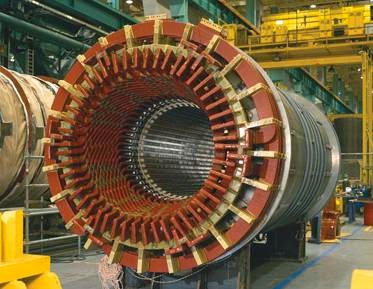
5000hp Motor Rewinding
↧
↧
Alternator Assembly
1-Rear End Of Shield
2-Stator ASSY
3-Front End Of Shield
4-Front Fan
5-Pully
6-Nut
7-Front Bearing
8-Rotor ASSY
9-Internal Fan
10-Regulator
11-Rear Bearing
12-Connector
13-Brush
14-Rectifier
15-Socket
16-Battery Terminal
2-Stator ASSY
3-Front End Of Shield
4-Front Fan
5-Pully
6-Nut
7-Front Bearing
8-Rotor ASSY
9-Internal Fan
10-Regulator
11-Rear Bearing
12-Connector
13-Brush
14-Rectifier
15-Socket
16-Battery Terminal
↧
Coal Based Thermal Power Plant
A coal-fired power station produces electricity, usually for public consumption, by burning coal to boil water, producing steam which drives a steam turbine which turns an electrical generator.
Coal is a relatively cheap fuel with some of the largest deposits in politically stable regions (China, India and the US) thus generally offering a more stable supply than natural gas and oil, the largest deposits of which are located in the more politically volatile Persian Gulf.
Coal is a relatively cheap fuel with some of the largest deposits in politically stable regions (China, India and the US) thus generally offering a more stable supply than natural gas and oil, the largest deposits of which are located in the more politically volatile Persian Gulf.
Why a Coal-fired power plant?
Coal-fired power plants are a proven, reliable and efficient way to generate electricity, and are critical to meeting power-grid demand. The basic construction of single reheat large steam turbines for coal-fired power plants was established over 30 years ago. This construction, designed originally for operating at conventional steam conditions, has achieved very high standards of reliability and operability through continuing development and feedback of operating experience. The same basic design therefore provides a very sound reference base for high output applications at supercritical operating conditions taking advantage of advanced materials and design refinements. Advanced pulverized-coal-fired power plants are well suited for mid-range power supply and support the grid system to avoid blackouts. Coal's value as a power plant fuel is greatly enhanced by its ability to supply power during peak power demand -- as base power -- and off-peak power demand.Diagram of a typical coal-fired thermal power station
Image may be NSFW.
Clik here to view.![undefined]()
Clik here to view.

| 1. Cooling tower 2. Cooling water pump 3. Transmission line (3-phase) 4. Unit transformer (3-phase) 5. Electric generator (3-phase) 6. Low pressure turbine 7. Boiler feed pump 8. Condenser 9. Intermediate pressure turbine | 10. Steam governor valve 11. High pressure turbine 12. Deaerator 13. Feed heater 14. Coal conveyor 15. Coal hopper 16. Pulverized fuel mill 17. Boiler drum 18. Ash hopper | 19. Superheater 20. Forced draught fan 21. Reheater 22. Air intake 23. Economizer 24. Air preheater 25. Precipitator 26. Induced draught fan 27. Chimney Stack |
↧
Electric Motor Simulation Using SPEED
This exploded view of an electric motor shows the surface temperature distribution and polyhedral mesh generated with STAR-CCM+ for a forced air cooling simulation.
↧
Testing of of electrical power system equipment
The testing of electrical power system equipment involves checking the insulation system, electrical properties, and other factors as they relate to the overall operation of the power system. Therefore, testing of electrical equipment can be divided into the following types:
• Solid insulation testing
• Insulating liquid testing
• Relay and protective device testing
• Circuit breaker time–travel analysis
• Grounding electrode resistance testing
• Fault gas analysis testing
• Infrared inspection testing
Solid Insulation Testing
Insulation can be either solid, liquid, or gaseous dielectric materials that prevent the flow of electricity between points of different potential. Insulation testing is done to determine the integrity of the insulating medium.
This usually consists of applying a high potential (hi-pot) voltage to the sample under test and determining the leakage current that may fl ow under test conditions. Excessive leakage current fl ows may indicate a deteriorated condition or impending failure of the insulation. Insulation testing can be performed by applying either direct current (DC) voltage or alternating 30 Electrical Power Equipment Maintenance and Testing current (AC) voltage. The testing of solid insulation with these voltages can be categorized as nondestructive testing and destructive testing, respectively.
The destructive test may cause equipment under test to fail or render it unsuitable for further service. Nondestructive tests are performed at low voltage stress, and the equipment under test is rarely damaged.
The AC hi-pot test is primarily a “go” or “no-go” test. The voltage is raised to a specified level. If the equipment fails or shows excessive leakage current, the equipment under test is unusable. If the equipment does not fail, it has passed the test. This test can only indicate whether the equipment is good or bad. It cannot indicate with what safety margin the test was passed. However, there are nondestructive tests that can be performed with AC voltage, such as power factor (PF), dissipation factor (DF), capacitance, etc.,.
.
The DC hi-pot test can indicate more than a “go” or “no-go” condition.
It can indicate that equipment is all right at the present time but may fail in the future. DC testing is done to obtain information for comparative analysis on a periodic basis. With dc testing, the leakage current is measured during the progress of the test and compared to leakage current values of previous tests. However, the DC hi-pot test is considered to be a destructive test if the test voltage is not applied in a predetermined control-voltage steps.
The DC voltage tests can be performed at lower voltages, which are nondestructive tests, such as insulation resistance, dielectric absorption ratio, and polarization index.
Insulating Liquid Testing
Insulating liquids used in transformers or other electrical apparatus are subject to deterioration and contamination over a period of time. These contaminants have a detrimental effect on the insulating properties of the fluid, as well as on the solid insulation system of the transformer winding. Basically, the elements that cause the deterioration of the insulating fl uids are moisture, heat, oxygen, and other catalysts that result in a chemical reaction that produces acid and sludge, which in turn attack the insulating fl uids. The main insulating fl uids that are in use today for transformers are oil, silicone, and RTemp and Wecosol. Askarel was used in the past, but its use was banned by federal regulations owing to its high toxicity; however, there may be installations that still may have this fl uid at their plant sites. Regular tests are recommended to monitor the condition of the insulating liquid. Samples should be taken from the transformers on periodic basis to perform various tests in accordance with American Society of Testing Materials (ASTM) methods.
Protective Device Testing
Protective device testing involves the testing and maintenance of protective relays, low-voltage draw out power circuit breakers, low-voltage molded-case Maintenance Strategies, Dielectric Theory breakers, and associated equipment such as instrument transformers and wiring. The function of protective relays and devices maintenance and testing is to assure that a particular breaker or protective relay is able to perform its basic protective function under actual operating conditions. The tests on relays, protective trip devices, and circuit breakers can be classified as commissioning tests, routine maintenance testing, and verification testing.
Circuit Breaker Time–Travel Analysis
The circuit breaker time–travel analysis test is performed to determine if the operating mechanism of the circuit breaker is operating properly.
This test is usually performed on medium- and high-voltage circuit breakers and depicts the position of breaker contacts with relation to time. This relationship can then be used to determine the operating speed of the circuit breaker for opening and closing and contact bounce, and the interval time for closing and tripping. The breaker operating time data can be used to evaluate the condition of mechanical parts of breakers, such as closing mechanism,springs, and shock absorbers.
Grounding Electrode Resistance Testing
The integrity of the grounding system is very important in an electrical power system for the following reasons:
To maintain a reference point of potential (ground) for equipment and personnel safety.
To provide a discharge point for traveling waves due to lightning
To prevent excessive high voltage due to induced voltages on the power system Therefore, to maintain ground potential effectiveness, periodic testing of grounding electrodes and the grounding system is required.
Fault Gas Analysis Testing
Fault gas analysis testing comprises of dissolved gas analysis and total combustible gas tests. The dissolved-gas analysis provides information on the individual combustible gases dissolved in the insulating oil. The total combustible fault gas analysis test provides information on incipient faults in oilfilled transformers by measuring the total combustible gases present in the nitrogen cap of the transformer. Because of excessive heat due to loading of Electrical Power Equipment Maintenance and Testing the transformer, or arcing and sparking inside the transformer insulating oil, some of the oil in the transformer decomposes and generates combustible gases, which then are dissolved in the oil, and eventually become liberated where they mix with the nitrogen above the top oil.
Infrared Inspection Testing
There are many different devices available using infrared technology to check hot spots in switchgear and other energized parts of the power system.
They are very useful in routine maintenance and inspection for
finding bad connections and joints and overloaded terminals or lines.
↧
↧
Dielectric Loss
All solid and liquid insulations have some measurable loss since there is no perfect insulator. These losses are usually very small in the insulations typically used in electrical equipment and apparatus, and these losses vary as the square of the applied voltage. Gaseous insulations, such as air, do not have a measurable loss until they become overstressed or ionized.
Dielectric loss is measured in watts (resistive components) and is a measure of energy dissipation through and over the surface of the insulation. The dielectric losses of most insulations increases with increase in temperature, moisture, and corona. Insulations may fail due to the cumulative effect of temperature, that is, rise in temperature causes an increase in dielectric loss which in turn results in a further rise in temperature. This phenomenon is self-perpetuating and continues until the insulation fails.
↧
PF and DF
The PF of insulation is defined as the ratio of watt loss to total charging volt-amperes, or the cosine of the angle q between total current vector (IT) and the impressed voltage vector. It is a measure of the energy component (resistive component) of the charging current. The DF is defined as the ratio of the watt loss to charging amperes, or the tangent of the angle d between the total current vector and the capacitive current vector. The angle d is the complementary angle of the PF angle q. Although, the charging volt- amperes and watt loss increase as the volume of insulation being tested increases at a given test voltage, the ratio of watt loss to the volt-amperes (PF or DF) remains the same regardless of the volume of insulation tested. Therefore, the basic relationship of PF or DF eliminates the effect of the volume of insulation that is, the size of the electrical equipment or apparatus tested. This simplifies the problem of establishing normal insulation values for most types of electrical equipment.
↧
Insulation as a Capacitor
Capacitance
In a capacitor, the charge Q (amount of electricity) is proportional to the voltage E. The expression for this relationship can be written as
where C is a constant called capacitance. The capacitance of any electrical equipment, including capacitors, may be calculated from their geometry.
(a) Parallel-plate air capacitor and (b) parallel-plate capacitor with dielectric material.
A capacitor in its most simple form is the parallel-electrode air capacitor as shown in Figure. The capacitance of such a capacitor can be calculated by the following formula:
where
- A is the area between the electrodes
- d is the thickness of the insulation (spacing between the electrodes)
- K is the dielectric constant of the insulation (air)
The dielectric constant (K) of air is practically unity and the dielectric constant of the other insulation materials is defi ned in terms of air or vacuum.
Table gives the dielectric constant values for most common types of insulating materials.
In cases where the geometry of the electrical equipment is simple and known, capacitance can be calculated mathematically. In the majority of cases, however, most insulation’s geometry is usually too complex and not well-enough understood to derive a reliable calculation of capacitance mathematically.
Insulation as a Capacitor
A perfect insulator can be represented by an ideal capacitor as shown in Figure. However, all electrical equipment insulation have losses and therefore an insulator is not a pure capacitor. Thus, the electrical circuit of a practical insulator can be represented by a capacitor with a small resistance in parallel with it, as shown in Figure.
The nature of insulation materials is such that 60 Hz current does not easily flow through them and therefore their purpose is to guide the current to the inside of the conductor. When voltage is applied to the conductor, two fields are established; one due to the current fl ow (magnetic field) and the other due to the voltage (dielectric or electrostatic field). The lines of magnetic flux around the conductor are concentric circles, whereas the lines of the dielectric flux around the conductor are radial. The resulting voltage stress due to the dielectric field varies inversely with the distance between equipotential lines.
The dielectric constant of an insulator is an indication of how much dielectric flux the insulation will allow through it. Under identical conditions insulation with a higher dielectric constant will pass more dielectric fl ux through it than another insulation having a lower dielectric constant. The dielectric constant for most commercial insulations varies from 2.0 to 7.0 as indicated in Table. It should be noted that the dielectric constant of water is 81 and generally when insulation becomes wet, its dielectric constant increases along with its capacitance, thus resulting in greater dielectric loss.
An ideal insulation can be represented as a capacitor because its behavior is similar to that of a capacitor. Two of the most common configurations considered for insulators are parallel-plate and cylindrical capacitors. For example, the parallel- plate capacitor represents an insulation system of a transformer or a machine winding, whereas the cylindrical capacitor represents an insulation system of a cable or a bushing.
In a capacitor, the charge Q (amount of electricity) is proportional to the voltage E. The expression for this relationship can be written as
Q = CE
where C is a constant called capacitance. The capacitance of any electrical equipment, including capacitors, may be calculated from their geometry.
(a) Parallel-plate air capacitor and (b) parallel-plate capacitor with dielectric material.
A capacitor in its most simple form is the parallel-electrode air capacitor as shown in Figure. The capacitance of such a capacitor can be calculated by the following formula:
where
- A is the area between the electrodes
- d is the thickness of the insulation (spacing between the electrodes)
- K is the dielectric constant of the insulation (air)
The dielectric constant (K) of air is practically unity and the dielectric constant of the other insulation materials is defi ned in terms of air or vacuum.
Table gives the dielectric constant values for most common types of insulating materials.
In cases where the geometry of the electrical equipment is simple and known, capacitance can be calculated mathematically. In the majority of cases, however, most insulation’s geometry is usually too complex and not well-enough understood to derive a reliable calculation of capacitance mathematically.
Dielectric Constant of Insulating Materials
Insulation as a Capacitor
A perfect insulator can be represented by an ideal capacitor as shown in Figure. However, all electrical equipment insulation have losses and therefore an insulator is not a pure capacitor. Thus, the electrical circuit of a practical insulator can be represented by a capacitor with a small resistance in parallel with it, as shown in Figure.
The nature of insulation materials is such that 60 Hz current does not easily flow through them and therefore their purpose is to guide the current to the inside of the conductor. When voltage is applied to the conductor, two fields are established; one due to the current fl ow (magnetic field) and the other due to the voltage (dielectric or electrostatic field). The lines of magnetic flux around the conductor are concentric circles, whereas the lines of the dielectric flux around the conductor are radial. The resulting voltage stress due to the dielectric field varies inversely with the distance between equipotential lines.
The dielectric constant of an insulator is an indication of how much dielectric flux the insulation will allow through it. Under identical conditions insulation with a higher dielectric constant will pass more dielectric fl ux through it than another insulation having a lower dielectric constant. The dielectric constant for most commercial insulations varies from 2.0 to 7.0 as indicated in Table. It should be noted that the dielectric constant of water is 81 and generally when insulation becomes wet, its dielectric constant increases along with its capacitance, thus resulting in greater dielectric loss.
An ideal insulation can be represented as a capacitor because its behavior is similar to that of a capacitor. Two of the most common configurations considered for insulators are parallel-plate and cylindrical capacitors. For example, the parallel- plate capacitor represents an insulation system of a transformer or a machine winding, whereas the cylindrical capacitor represents an insulation system of a cable or a bushing.
↧
Characteristics of Dielectrics (Insulation)
Dielectrics (insulation) for electrical equipment and apparatus is used for many different applications. It is expressed for a wide range of environmental conditions such as temperature, moisture, chemicals, other contaminants, and exposure to weather. One major factor affecting insulation life is thermal degradation, although moisture, contamination, voltage stress, and other factors may also contribute to its degradation. In addition, the life of an insulating material depends on the degree of loading, the type of service to
which the equipment is subjected, the care it receives during installation and operation, and mechanical vibration and forces to which it is subjected.
The properties of insulating materials that are necessary and desirable are surface leakage, resistance to moisture, chemicals, oils and other contaminants,and mechanical properties. The important electrical characteristics of insulation are volume resistivity, PF, DF, capacitivity, dielectric constant, and dielectric strength. These characteristics, except for dielectric strength, can be assessed by nondestructive testing. These tests are
1. AC dielectric loss
2. PF or DF (tan d )
3. Capacitance
4. AC resistance
5. Radio interference voltage (RIV)
6. DC insulation resistance
7. DC dielectric absorption
↧
↧
Air-cooled SGen5-1000A generator.
Air-cooled SGen5-1000A generator at Charlotte CCPP in North Carolina, USA. Copyright Siemens AG, Munich-Berlin
↧
Insulating Materials for Electrical Power Equipment
There are number of materials which are used either separately or as a combination of composite products to form an insulation system for electrical power equipment. The basic materials selected for insulation systems are selected based on their ability to withstand varied electrical, mechanical,and thermal stresses during the life of the equipment. Listed below is a partial summary of the materials and products used for insulating electrical power equipment.
Rigid Laminates Sheet, Rod, and Tube
Canvas-• based phenolic laminate
• Paper-based phenolic laminate
• Glass melamine laminate
• Glass silicone laminate
• Glass epoxy laminate
• Cogetherm mica-based laminate
• Mica epoxy laminate
• Transite HT and NAD-11 high-temperature cement boards
Glass Polyester Products
• Glass polyester sheet
• Glass polyester channels and angles
• Glass polyester stand-off insulators
• Glass polyester rods
• Specialty glass polyester
Flexible Laminates and Films
• Diamond-coated kraft paper
• Vulcanized fiber sheets, rods, and tubes
• Kraft pressboard products
• COPACO rag paper
• Quin-T family of flexible laminates
• Melinex polyester film
• Mylar polyester film
• Dacron–Mylar–Dacron
• Kapton polyimide film
• Nomex aramid paper
• Nomex–Polyester–Nomex
• Rag Mylar and Rag–Mylar–Rag
Over the years organic insulating materials have been replaced with inorganic materials and this progression is still continuing. There are number of organic and inorganic insulating materials that are used in electric power equipment. Although this listing discussed in this section is somewhat long, it is not all encompassing because the choices of available insulating materials are many. The use of the trade names in the listing given here does not represent a particular brand preference but are included for clarity. The characteristics of various insulating materials are discussed as follows.
Cotton: Cotton has been used extensively in electrical insulation because of its low cost, strength, elasticity, fl exibility, and adaptability to size requirements and manufacturing process. However, cotton has a tendency to absorb moisture and limited thermal capability. Cotton is always used with varnish or resin impregnation to obtain good dielectric strength and moisture resistance.
The use of cotton is restricted to 105°C (Class A insulation system)
because temperatures higher than class A cause decomposition of the cotton fibers with resulting embrittlement and loss of mechanical strength.
Cotton fabrics: There are many varieties of treated fabrics that are fundamental Class A insulating materials. Untreated cotton fabrics that have been thoroughly dried are used for oil transformer insulation. These fabrics are quickly impregnated when the transformer is fi lled with oil, thereby providing excellent physical and dielectric properties. Two most commonly used fabrics are tan-varnish treated cloths and black-varnish treated cloths.
Paper: Many types of paper are used in insulating electrical equipment.
These varieties include Japanese tissues, cotton rags, manila (hemp), the kraft (wood pulp), jute, fi shpaper (gray cotton rag), fuller board, and the like. Rag and kraft paper often called transformer paper is used to separate windings in a transformer or in applications where there are no sharp edges that might poke through the relatively weak paper. Fishpaper is usually vulcanized and often laminated with Mylar giving it excellent resistance to tear and puncture.
The paper–Mylar laminates resist soldering heat better since paper does not melt and the Mylar resist moisture best. Papers made with temperature resistance nylon and/or glass weaves have excellent electrical properties and good temperature resistance. Paper posses similar properties as cotton cloth, but because of its structure it has higher dielectric strength than cotton.
The thermal stability and moisture absorption properties of paper are similar to cotton; however, paper does not possess the high mechanical strength of cloth. Untreated paper has little insulating value because of its extreme tendency to absorb moisture.
Asbestos: Recent restriction placed by Environmental Protection Agency (EPA) and OSHA has limited the use of the asbestos as an insulating material.
It is used in the form of asbestos paper or asbestos tape, asbestos mill board or asbestos lumber for electrical insulating purposes. In such forms, it may contain 10%–20% wood pulp and glue to give it strength. Asbestos is generally heat resistance, but if heated excessively asbestos loses its hygroscopic moisture and therefore becomes brittle. Asbestos absorbs moisture from the surrounding atmosphere which makes it a less effective insulator.
Glass: Glass insulation comes in a wide variety of forms including solid glass, fiber tapes, fi berglass sheets and mats, woven tubing and cloth, and various composites. The most common form of glass used in electrical equipment is fiberglass. Fiberglass is available as fi berglass yarns for insulating materials. Today, fi berglass cloths and tapes are widely used in high temperature applications. Two types of fi berglass yarns commonly used for electrical insulation are continuous fi lament and staple fi ber yarns. The continuous filament yarns have the appearance of natural silk or linen whereas the staple fiber yarns exhibit a considerable degree of fuzziness similar to wool yarns. Fiberglass has advantages of high thermal endurance, high chemical resistance, high moisture resistance, good tensile strength, and good thermal conductivity when impregnated or coated with varnish or resin.
Glass fibers exhibit poor abrasion resistance therefore fi bers must be lubricated before they are woven into cloth. Varnish treatment of glass cloths greatly increases the abrasion resistance. Untreated glass cloth is used primarily as a spacing insulation and when the cloth is impregnated and coated with an insulating resin or varnish it becomes an effective dielectric barrier.
Among the many uses of fi berglass are covering of wire, binder tapes for coils, and backing for mica tapes. It is also used as ground insulation and insulation for stator coil connections, leads, ring supports, etc. when treated with oleorresinous and other varnishes. Fiberglass, varnish-treated fiberglass, and non woven forms are thermally stable, resistance to solvent depending on the type of varnish used. It is more secure spacer insulation than cotton or paper.
Synthetic textiles and films: Numerous synthetic fi ber textiles are in use as electrical insulation. These are either continuous monofi laments of resins, or short fi bers made of resins that are spun into threads and woven into fabrics.
They have to be coated or impregnated with varnish to become effective dielectric barriers. The thermal ability of these materials lies between cellulose fabrics and glass fabrics and depends on the type of resin coating or impregnating material used more than their own characteristics. Examples of synthetic fi ber cloth and mats are Dacron, other polyesters, aromatic nylons, such as Nomex, Kelvar, and others. They have thermal stability, solvent resistance, and lack of fusibility. Several polyester fi lms exhibit excellent electrical and physical properties, such as Mylar which enjoys widespread use in a variety of insulation systems.
Polyester films: They are used at temperatures above 105°C–125°C and have fair solvent resistance. Some specially formulated polyester varieties are used for service up to 180°C. The common uses of polyester fi lms such as Mylar and others are slot liners, layer insulation in transformers, capacitors, and as laminated backing of paper insulation.
Aromatic polyimide (Kapton, Nomex, and others): It is used at temperatures of 180°C–220°C. It has excellent resistance to solvents and has good heat resistance and superb mechanical and electrical properties. Nomex is a Dupont aromatic polyamide with a temperature rating above 220°C and has high voltage breakdown strength.
Polyolefins: Polypropylene and polyethylene are two known polyolefins that are available with ultrahigh molecular grade matching the strength of steel.
Polypropylene is used for insulation not to exceed temperatures above 105°C whereas polyethylene film has limited use such as class O insulation system since it softens at temperatures higher than 70°C.
Polycarbonate: Common trade names for it are Lexan and Merlon and are used for insulation system rated at temperatures 105°C and below. It has excellent electrical insulating properties and has good oil resistance but poor solvent resistance.
Polysulfone: This is another thermoplastic that include polyetherimide, polyamide, and polyphenylene with trade names like Noryl, Udel, Vespel, and Torlon. These materials are used at temperatures from 105°C to 130°C and have good oil resistance but not chlorinated solvent resistance.
Polytetrafluoroethylene (Teflon): It is an excellent high-temperature insulation with excellent electrical insulating properties and is used at temperatures of 220°C and higher. Teflon tubing and wire insulation is available in a variety of colors and typically feels slippery. It has good resistance to moisture.
Nylon: Nylon has good resistance to abrasion, chemicals, and high voltages and is often used to fashion electromechanical components. Nylon is extruded and cast and is filled with a variety of other materials to improve weathering, impact resistance, coefficient of friction, and stiffness.
Phenolics: Phenolic laminated sheets are usually brown or black and have excellent mechanical properties. Phenolics are commonly used in the manufacture of switches and similar components because it is easily machined and provides excellent insulation. Phenolic laminates are widely used for terminal boards, connectors, boxes, and components.
Polyvinylcloride (PVC): PVC is perhaps the most common insulating material.
Most wiring is insulated with PVC including house wiring. Irradiated PVC has superior strength and resistance to heat. PVC tapes and tubing are also quite common. Electrical and electronic housings are commonly molded from PVC.
Acrylic: Lucite and Plexiglas are trade names for acrylic which has widespread use where toughness and transparency are required.
Beryllium oxide: A hard white ceramic-like material used as an electrical insulator where high thermal conductivity is required. Beryllium oxide is highly toxic in powder form and should never be fi led or sanded and consequently has fallen out of common use. Power semiconductor heat sinks can still be found with beryllium oxide spacers for electrical insulation.
Ceramic: Ceramics are used to fabricate insulators, components, and circuit boards. The good electrical insulating properties are complemented by the high thermal conductivity.
Melamine: Melamine laminated with woven glass makes a very hard laminate with good dimensional stability and arc resistance. It is used in combination with mica to form rigid fiber laminates.
Mica: Mica sheets or stove mica is used for electrical insulation where high temperatures are encountered. Two kinds of mica, Muscovite (white or India mica) and phlogopite (amber mica) are generally used for insulating purposes.
Mica and reconstituted mica paper are inorganic and infusible. Mica has high dielectric strength, high insulation resistance, low dielectric loss, good mechanical strength, good dielectric constant (specific inductive capacity), and good heat conductivity. Puncture resistance is good but the edges of the mica should be fl ush against a fl at surface to prevent flaking.
Mica finds uses in composite tapes and sheets which are useful up to 600°C with excellent corona resistance. Sheets and rods of mica bonded with glass can tolerate extreme temperatures, radiation, high voltage, and moisture. It is also available as mica paper where tiny mica flakes are made into paper like structure and reinforced with fiber, glass, or polyester.
Rigid fiber laminates: They are made of layers of cloth (glass, cotton, polyester, etc.) or paper with resin (phenolic, melamine, polyester, and epoxy) impregnation. They are supplied as thermosetting, thermoforming, and postforming materials used as insulators.
Micarta: It is rigid fiber laminate made of cloth, paper, or wood saturated with either a synthetic or organic resin, and then compressed under heat.
This process makes the resin permanently hard and therefore Micarta becomes impermeable to heat, pressure, and solvents. Originally, Micarta was developed as an insulator but today it has many applications. Micarta mechanically strong, rigid, and nonmagnetic. It is less susceptible to moisture and most acids. Micarta is used for insulating washers, controller panels and cams, slot wedges, brush rigging, bus bar supports, insulating barriers, and transformer insulation.
Synthetic resins: Synthetic resins are used extensively in varnish manufacture.
The polyester and epoxy types are representative of heat hardening
resins. Varnishes containing such resins are thermosetting and will cure by heat alone and do not require oxygen. Other synthetic resins are phenolic resins suitable for molding and bonding; alkyd type resins are being substituted for the old black varnishes and compounds; melamine resins are used for making laminates and molded compounds; and vinyl resins are used in the compounding of plastics and rubber substitutes.
Varnish: Insulating varnishes are of great importance in the maintenance of electrical equipment and apparatus. An insulating varnish is a chemical compound of synthetic resins or varnish gums and drying oils, having high dielectric strength and other properties that protect electrical equipment. Varnishes provide important insulating and protective functions, which are rotect the insulation and equipment against moisture
• Electrically and thermally enhance other insulating materials
• Add mechanical strength to other components of the insulation
• Minimize the accumulation of dust and contaminants, and improve heat dissipation by filling voids
• Enhance and increase the life of insulating materials
Adhesive-coated tapes: Many of the insulating films and fabrics described above can be obtained and used with adhesive backing that are usually thermoses or heat curable.
Rubber: Natural or Buna S rubber is not normally used for insulation these days because it is affected by ozone and has poor thermal stability.
On the other hand, butyl and ethylene propylene rubbers are ozone resistance and more thermally stable. These are used for molded parts, cable insulation, and lead insulation in motors.
Silicone rubber: A variety of silicone foam rubbers are available as an insulating material. Silicone rubbers exhibit characteristics of superb chemical resistance, high-temperature performance, good thermal and electrical resistance, long-term resiliency, and easy fabrication. Liquid silicone rubbers are available in electrical grades for conformal coating, potting, and gluing.
Silicone rubbers have excellent thermal stability and ozone resistance, but only fair mechanical strength and abrasion resistance.
Silicone/fiberglass: Glass cloth impregnated with a silicone resin binder makes an excellent laminate with good dielectric loss when dry.
↧
BALANCING OF ROTATING EQUIPMENT COMPONENTS
BALANCING OF ROTATING EQUIPMENT COMPONENTS |
To give an overall idea about the balancing of Rotating Equipment components to the Maintenance and Operations personnel.
Scope:
The scope of the manual is to explain the purpose of balancing the rotating equipment components and to give a brief information about the balancing procedures, balancing machines and the prevalent balancing standards.
Terminology
1.1 Balance Quality Grade: G Xxx
1.2 Center Of Gravity
1.3 Principal Inertia Axis
1.4 Correction Plane (For Balancing)
1.5 Static Unbalance
1.6 Couple Unbalance
1.7 Critical Speed
1.8 Dynamic Unbalance
1.9 Rotor
1.10 Rigid Rotor
1.11 Flexible Rotor
1.12 Specific Unbalance
1.13 Residual Unbalance
1.14 Permissible Residual Unbalance (U per )
1.15 Units Of Unbalance Introduction
2.1 Reasons For Balancing
2.2 Causes Of Unbalance
3 Safety & Environmental Precautions
3.1 Safety Of The Balancing Machines
3.2 Safety While Balancing The Rotors
3.3 Safety During The Field Balancing Of The Rotating Equipment :
4 BALANCING MACHINES:
4.1 Gravity Balancing Machines:
4.2 Centrifugal Balancing Machines:
4.2.1 SOFT BEARING BALANCING MACHINES
4.2.2 HARD BEARING BALANCING MACHINES :
5 BALANCING METHODS
5.1 Preparation For Balancing
5.2 Shop Balancing
5.2.1 SYMMETRICAL ROTOR
5.2.2 SYMMETRICAL ROTOR WITH OUTBOARD BALANCING PLANES –
5.2.3 OVERHUNG AND NARROW ROTORS
5.3 High Speed Balancing –
5.4 Field Balancing-
6 BALANCING STANDARDS.
References
1 Terminology
1.1 Balance Quality Grade: G Xxx
For rigid rotors, G , is the product of specific unbalance , e, and rotor maximum service angular velocity. Service angular velocity is nothing but the service RPM expressed in radians per second.( w )
G = e * w
1.2 Center Of Gravity –
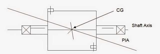
The point in a body of a rotor through which the resultant of the weights of its component particles passes for all orientations of the body with respect to a gravitational field is called the center of gravity - C.G.
This can also be described as the point about which the rotor’s weight is equally distributed.
1.3 Principal Inertia Axis –
A line about which the rotor weight is equally distributed is known as Principle Inertia Axis ( PIA in short ) . It is obvious that the Center of Gravity ( CG ) is always on the Principal Inertia Axis ( PIA )
1.4 Correction Plane (For Balancing)-
The plane perpendicular to the shaft axis of a rotor in which correction for unbalance is made. The correction can be in the form of material addition, or material removal, or any change in the weight distribution in this plane.
1.5 Static Unbalance
It is that condition of unbalance for which the central principal axis is displaced only parallel to the shaft axis.
1.6 Couple Unbalance
It is that condition of the unbalance for which the central principal axis intersectsthe shaft axis at the center of gravity.
1.7 Critical Speed
It is that speed at which a system resonance is excited. The resonance may be of journal supports ( rigid mode ) or flexure of the rotor ( flexural mode ). There are many critical speeds for a rotor and they are denoted like first, second, third in lateral and torsional modes.
1.8 Dynamic Unbalance
It is that condition of unbalance for which the central principal axis ( PIA ) is not parallel to and does not intersect the shaft axis. Obviously the CG is not on the shaft axis as well .It is usually a combination of the static and couple unbalance. This is the type of unbalance, which is usually found in practice in the unbalanced rotor.
The Dynamic unbalance is equivalent to two unbalance vectors in two specified planes, which completely represent the total unbalance of the rotor.
Dynamic unbalance may also be resolved into a static and couple unbalance vectors whose vector sum is also equal to the total unbalance of the rotor.
1.9 Rotor
A body capable of rotation, which generally has journals supported by the bearings.
1.10 Rigid Rotor
A rotor is considered rigid if its unbalance can corrected in any two correction planes. After the correction, the residual unbalance does not change significantly at any speed up to the maximum service speed. In other words it also means that the rotor service speed is much lower than its first lateral critical speed.
1.11 Flexible Rotor
A rotor that does not satisfy the definition of the rigid rotor is known as a flexible rotor. It also means that the rotor needs to be balanced in such a way that it remains reasonably balanced while it attains the maximum service speed. The rotor of this class runs at least above the first lateral critical speed. While passing through the critical speeds there is some amount of elastic deflection depending on the mode shapes. The correction planes are so selected that, the elastic deflection has no severe impact on the balance of the rotor, at that speed range.
1.12 Specific Unbalance
The static unbalance U divided by the rotor mass M. This will also yield the value for mass eccentricity, which is denoted by “ e“
1.13 Residual Unbalance
The unbalance of any kind that remains after the balancing of the rotor is known as residual unbalance. This must be less than the permissible value, as per the balancing standers adopted for that class of rotor.
1.14 Permissible Residual Unbalance (U per )
The maximum residual unbalance permitted for a rotor or for a correction plane for the rotor is termed as permissible residual unbalance. This is expressed as
U per = eper x m , Where m is the mass of the rotor.
1.15 Units Of Unbalance
Unbalance is measured in gram-millimeters or ounce inches. It simply means the quantity of unbalance mass (m) , multiplied by the distance ( R ) from shaft axis.
As an example, an unbalance of 15 gm at 100 mm radius will introduce an unbalance of ( 15 x 100 ) = 1500 gm-mm , in that plane.
This is independent of speed of rotation. However the same unbalance will produce higher centrifugal force if the speed of rotation increases. In fact the centrifugal force generated due to unbalance is proportional to the “ square “ of RPM. ( F = m x R x W x W)
2 Introduction
One of the basic problems in the rotating machinery is the unwanted vibration. Since the rotor rotates, if it is out of balance, vibration will be present primarily because of the unbalance. This can corrected by balancing the rotor. There are many other reasons for balancing the rotors.
2.1 Reasons For Balancing
An unbalanced rotor will cause vibrations, and may result into premature bearing failures, seal failures, noisy operation, shaft & coupling damage, structural vibrations and failures. This depends on the degree of unbalance and also the tolerance of the various components to theses forces produced due to unbalance. Therefore balancing of the rotor is required for the following reasons-
Ø Reduce stresses on the rotor shaft, bearings, coupling, gears, frame, foundations, adjoining structure and machinery, etc.
2.2 Causes Of Unbalance
Ideally speaking, a fully machined (from outside and inside) and absolutely symmetrical rotor should be inherently balanced in the “ as machined ” condition, even if it is not “ balanced “ after manufacturing. However this is rarely achieved. The reasons are as follows-
Ø Anisotropy of the material due to voids in casting, inclusions and blowholes in the welding, metallurgical differences, and so on.
Ø Geometrical differences resulting in non- symmetry
Ø Distortion during operation because of mechanical forces, thermal distortion, looseness at higher speeds due to centrifugal forces
Ø Corrosion, erosion and the deposits on the rotating parts in service
3 Safety & Environmental Precautions
3.1 Safety Of The Balancing Machines :
The balancing machines handle rotating components like rotors of pumps, turbines and compressors. The lifting and shifting of these parts should be done by qualified trained personnel and by using the load tested lifting equipment like cranes, slings, eyebolts and shackles.
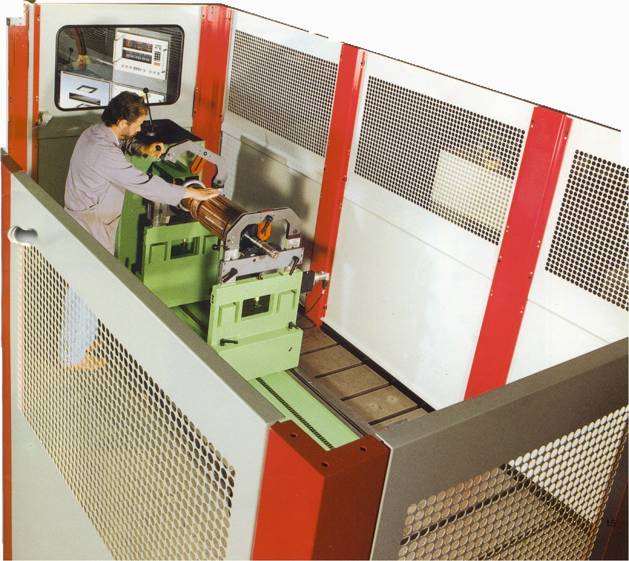
When the rotors are balanced, they are rotated at a certain speed. The area around the machine should be well cordoned and should be kept safe for the personnel working nearby. The rotor should be thoroughly checked for any loose part or the damage so as to exclude any possibility of loose part on the rotating component.
Please see the photograph of the Balancing Machine equipped with the safety barriers and the enclosure, for the safety.
The rotor has to be coupled very carefully with the balancing machine coupling. The error at this point results in a faulty balancing and a chance of rotor getting uncoupled while being rotated in the balancing machine.
Every balancing machine has a safe working limit as far as the maximum speed and the maximum weight of the rotor it can safely handle. The balancing machine should be strictly used within this limit. Exceeding the limit may result in damage to the machine, rotor and the personnel operating the machine, etc.
3.2 Safety While Balancing The Rotors :
The unbalance correction usually carried out by adding or removing the mass on the rotor. The addition of the mass can be achieved by welding, bolting, riveting etc. This operation should be performed using all the PPEs (personal protective equipment) like hand gloves, welder’s glasses and face shields, etc.
The mass can be removed by grinding, machining etc. The appropriate PPEs life, face shields, hand gloves, etc must be used. Secondly, if the correction is done, while the rotor is still on the rollers of the balancing machine, it should be positively ensured that the machine does not start spinning the job accidentally.
A care must be taken to remove the mass gradually as per the recommended practices and keep the strength and integrity of the rotor in mind while doing any such operations. The addition of mass or removal of mass should not result in weak spot or should not cause a major disturbance to the flow in the equipment.
3.3 Safety During The Field Balancing Of The Rotating Equipment :
Some of the large and slow speed rotors like boiler fans, conveying blowers, and Cooling tower fans, etc are balanced at site for convenience. The equipment is run for a short time to take the vibration and phase readings. The correction is made in steps by adding the mass at a specific radius and angle. Extreme care is necessary while adding the masses and also while taking the readings. Usually three or even more trials are necessary in the field balancing. After every trial followed by correction on the rotor the equipment is started for taking the readings. Under no circumstances the equipment should accidentally start when the job is being carried out on the rotor.
The addition of the mass can be achieved by welding, bolting, riveting etc. This operation should be performed using all the PPEs (personal protective equipment) like hand gloves, welder’s glasses and face shields, etc. Proper work permits, hot work permits and positive isolation of the equipment while the weights are being added on the rotor must be strictly followed. All the concerned personnel should be informed before starting the job and also after completing the balancing job.
4 BALANCING MACHINES:
The purpose of the balancing machine is to determine the magnitude and angular position of the unbalance in the plane of reference called the balancing plane.
4.1 Gravity Balancing Machines:
This type of machine includes the Horizontal ways, knife-edges and the roller stand. The rotor to be balanced is placed on it and rolled slowly so that the heavy side rolls down due to gravity. This machine is good enough only to detect the static unbalance and useful for narrow rotors only. This is a useful step for the subsequent dynamic balancing, because the statically balanced rotor with a reduced residual unbalance is easy to balance on the dynamic balancing machines.
4.2 Centrifugal Balancing Machines:
The rotor is supported by the balancing machine bearings and rotated around a horizontal or vertical axis. The centrifugal balancing machine is capable of measuring the static unbalance (single plane) and static or couple unbalance (in two-plane machine). It should be noted that only a two plane rotating balancing machine can detect a couple and hence a dynamic unbalance. In these types of machines, the amplitude and phase of motions or reaction forces of rotating centrifugal force vector is sensed and measured and also indicated to the operator for the balance correction.
Two types of the centrifugal balancing machines are commonly used. They are called soft bearing machines and the hard bearing machines.
4.2.1 SOFT BEARING BALANCING MACHINES
The name “ soft bearing balancing machine “ is derived from the fact that these machine support the rotor to be balanced on the bearings which are very flexible. This allows the rotor and bearing pedestals to vibrate freely and generously in the direction perpendicular to the rotor axis. The resonance of the rotor system occurs at a speed much lower than the speed at which the actual balancing is carried out. Please refer the ”Phase angle and displacement amplitude versus rotational speed in the SOFT BEARING balancing machines” given below.
Phase angle and displacement amplitude versus rotational speed in the SOFT BEARING balancing machines
DETAILS OF VARIOUS COMPONENTS OF THE BALANCING MACHIUNES
HEIGHT ADJUSTABLE ROLLER CARRIAGE FOR ROTOR WITH THEIR OWN JOURNALS
SLEEVE BEARING SUPPORT FOR THE HIGH SPEED BALANCING OF ROTOR
4.2.2 HARD BEARING BALANCING MACHINES :
Hard bearing balancing machines are similar to the soft bearing balancing machines in construction. The only difference being their bearing supports are much stiffer in comparison. This results in a resonance of the rotating system occurring much above the balancing speed. The hard bearing balancing machine is therefore specially designed to be operated well below the resonance .
Phase angle and displacement amplitude versus rotational speed in the HARD BEARING balancing machine
Basically there are three types of balancing jobs encountered and the methods involved used for those types may be categorized as
Shop balancing
High Speed balancing
Field balancing
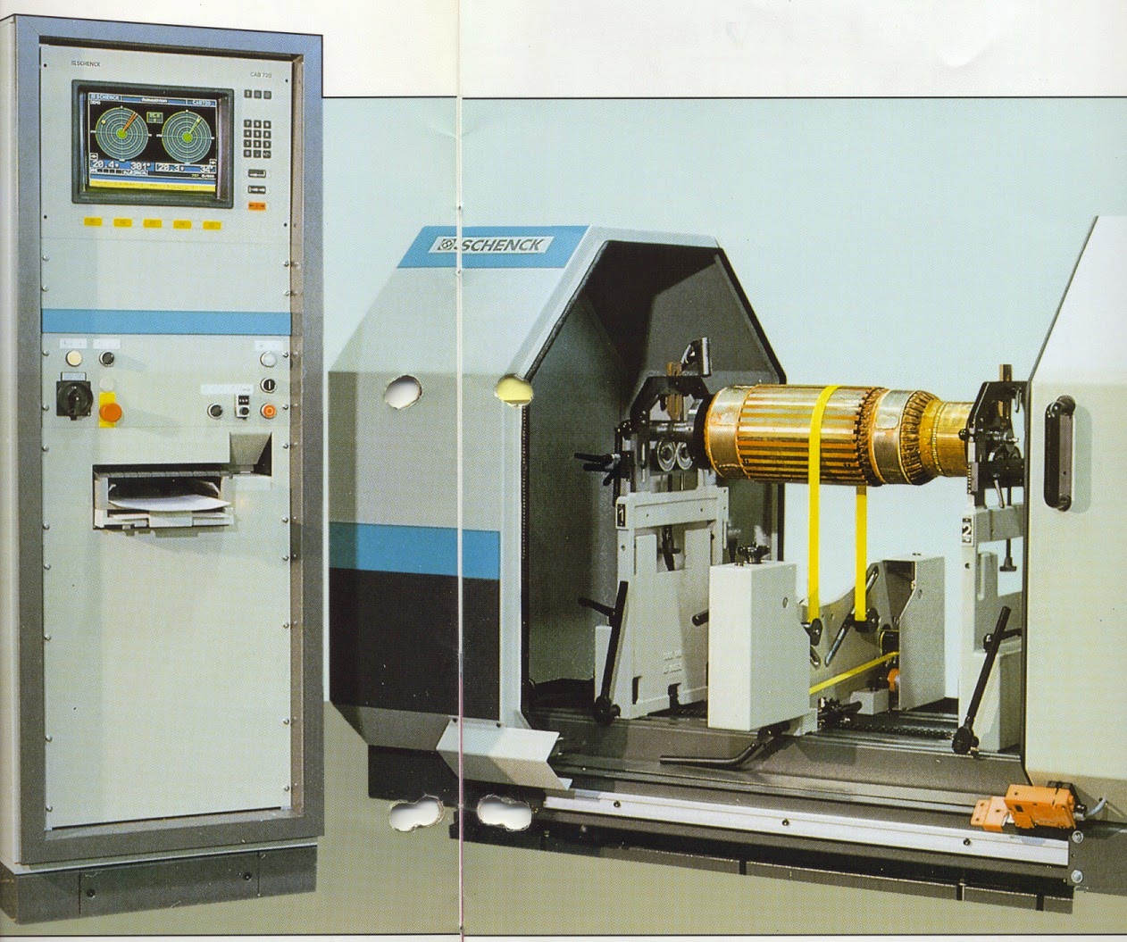
BALANCING A ROTOR ON A BELT DRIVEN BALANCING MACHINE
A VERY BIG FAN ROTOR BIENG BALANCED
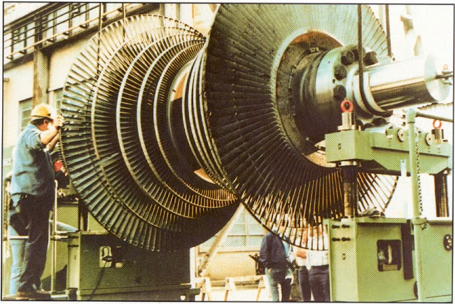
A BIG , VERY HEAVY STEAM TURBINE ROTOR BEING BALANCED
5.1 Preparation For Balancing
Before starting the balancing of a rotor few things are important to remember. The list is very long but some of the important points are highlighted below-
If the rotor to balanced is the one which was used in service, clean the rotor thoroughly and inspect for any damage, cracks, wear etc. A thorough degreasing followed by ash blasting or ceramic bead blasting is an ideal way to clean the rotor.
In case of a doubt, magnetic particle inspection or Dye Penetration test is helpful in determining the surface & subsurface flaws and cracks etc.
It is always a good idea to remove all the deposits, especially polymer deposits and the deposits on fan rotors, turbine blades, before balancing.
The straightness of the rotor shaft must be checked and the ovality, taper and wear on the journals must be measured. If the shaft is bent and the journals are not within the specified accuracy, there is no use of balancing in this case. These faults must be corrected first to achieve the accurate balancing.
The rotor assembly and fitment of the impellers and discs on the shaft must be checked for proper shrink fits, perpendicularity and axial location. No rotating part should be loosely installed on the shaft.
It is also important to measure the radial and axial runouts on the impeller discs and shrouds. This has to be within the limits specified. Any correction or machining required has to be done before the balancing. After balancing no corrections are possible .
The rotor is balanced by supporting the journals on the balancing machine rollers. Hence both the journals of the rotor as well as the rollers of the balancing machine have to be inspected and should be free of inaccuracy.
The compressor, fan and pump rotors must be balanced on the balancing machine by rotating them in their usual direction of rotation. Where as the turbine rotor is reverse rotated while balancing.
The rotor to be balanced must be a full assembly including the keys, the coupling half , any subassemblies like overspeed mechanism, lube oil pump driving gear and so on. This ensures that the full rotating assembly is precisely balanced as one single unit in the final balancing step.
5.2 Shop Balancing
Most of the rotors are balanced in the shop where they are manufactured. The Original Equipment Manufacturers who manufacture pumps , turbines and compressors , carry out the balancing of their rotors by this method. Depending on the size, weight and the speed of the equipment, different types of the balancing machines are used. In most of the cases the speed used to rotate the rotor is much less than the actual speed of the rotor. Depending on the shape of the rotor different methods are employed. Some of the shop balancing machines have direct drives and the rotor to be balanced is connected by a suitable end drive adapter, which connects the rotor to the driver by a universal joint. In some of the balancing machines, the drive is by a belt for spinning the rotor, as shown on the Universal Balancing machine on the previous page.
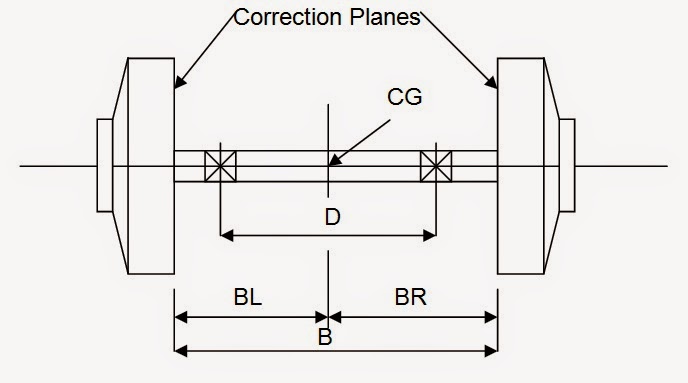
For balancing the rotor the important dimensions like the bearing span ( D), distance between CG and the correction planes ( BL & BR ), distance between bearing and the correction plane ( A ) must be measured and noted carefully.
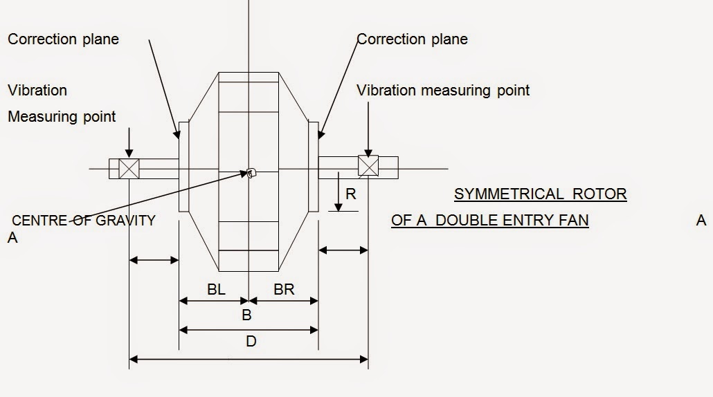
5.2.1 SYMMETRICAL ROTOR
The type of rotor that falls under this category must satisfy the following conditions
· Correction planes are within the bearings
· The distance “B” is greater than 1/3 of “ D”
· The correction planes are equidistant from the center of gravity CG and when the correction planes are not equidistant from the CG, the permissible unbalance calculated per plane should be in that proportion.
U per Left = Uper ( BR / B )
U per Right = U per ( BL / B )
This type of rotors are typically seen in double entry boiler fans etc. Please see the following figure.
5.2.2 SYMMETRICAL ROTOR WITH OUTBOARD BALANCING PLANES
These type of rotors are also popularly known as “ Dumb-bell” rotors.
The correction planes are equidistant from the center of gravity CG and when the correction planes are not equidistant from the CG, the permissible unbalance calculated per plane should be in that proportion.
U per Left = U per ( BR / B )
U per Right = U per ( BL / B )
This type of rotors is typically seen in turbo-expanders, integral gear air compressor rotors and so on.
5.2.3 OVERHUNG AND NARROW ROTORS
These are very common for the overhung fans and overhung pump impellers. These types of rotors are supported by two bearings and as compared to the impeller diameter the width of the impeller is very small making it a narrow rotor.
The following rules and conditions apply to the overhung and narrow rotors.
The distance between the correction planes is less than 1/3 the distance between the bearings. ( B < 1/3 D.)
The permissible dynamic bearing loads are assumed to be equal.
Couple corrections are made 180 degrees apart in their respective planes.
The plane for static corrections may be a third plane or either of the planes used for couple corrections.
Allocate per as static and couple residual unbalance as follows :
U per Static = U per / 2 * D / 2*C
U per Couple = U per / 2 * 3*D / 4*C
Permissible unbalance allocation for overhang and narrow impellers require that two-plane unbalance correction divided into static and couple unbalance equivalents.
5.3 High Speed Balancing
The high speed balancing or “ at speed balancing “ is done for high speed critical centrifugal compressors and turbines etc. It requires a very sophisticated set up and a balancing machine. These types of facilities are limited in number worldwide and they are very expensive as well.
The installation consists of a chamber capable of holding the rotor along with the bearing pedestals, and also a place for the balancing personnel to move inside for weight correction on the same rotor by machining, grinding, etc. The complete set up is in a bunker and the in an airtight chamber or enclosure. The chamber is connected to the vacuum pumps. The vacuum is maintained to avoid the airflow through the impeller. At very high speed the windage and friction will be very disturbing, and dangerous as well. Secondly it will require a prime mover of very high horsepower to spin the rotor at that speed. One more problem will be the heating up of the air inside the chamber. Rotating the rotor in a vacuum chamber solves all these problems. There are protection devices to safeguard against the vacuum failure.
Normally a variable speed drive or motor and gearbox combination is used. The balancing equipment are also very sophisticated and they include computerised system which calculates the unbalance and the angular position etc. It records the initial unbalance and also records all the stepwise corrections. It is worth noting that for balance correction, say by grinding, the rotor must be stopped and vacuum must be relieved. Again after the correction, the rotor must be tested in re-evacuated chamber. This makes the High Speed balancing a very time consuming, labour intensive and expensive operation.
It must be noted that all the rotors do not deserve such a stringent testing. The multistage, critical rotors, falling in the category of “ Flexible Rotors”, meaning operating above their first lateral (bending) critical speed, must be tested this way. This testing revels characteristics of the dynamic rotor response.
Please refer to the following pictures showing a complete set-up for high speed balancing. Note the enclosure, the bearings with pickups and the vacuum seals, etc. On these types of machines the critical multi-impeller rotors are also tested for what is popularly known as “ Over Speed Testing “.
5.4 Field Balancing
This is one more practical way of balancing the rotating equipment and the name of this method is due to the fact that it is done in the field. This is also suitable for big rotors rotating at lower speeds for example air blowers, fans, etc. Generally this method is used for small finer corrections and not the major adjusting. This is usually done when the machine vibrations show an increase and the cause is the imbalance. The rotors such as ID fans show “ out of balance “ after some use due to thermal distortion, corrosion, erosion, wear and tear and deposits etc. If the imbalance resulting due to such a problem is not very high, it can be corrected easily by “ field balancing”. It is much easier to do a field balancing than, de-coupling, opening the equipment, and taking out the complete rotor assembly, transporting from site to balancing facility and then fixing back the same way after the shop balancing.
Secondly, many of the equipment are so designed that a “ field balancing” provision is made on the rotor. Electric motors, air fan rotors, and sometimes even the steam turbines have a provision for adding the balance correction weights without removing the rotor from the casing. The end covers have widows to get access to the balance correction ring or slots in which the balance weights are added and fixed permanently so that they do not move in service.
In the field balancing, single plane, two-plane and multi plane balancing is possible. It depends on the shape of the rotor and the running speed. Very narrow overhung type rotors are balanced in the single plane. Relatively broad rotor life ID fan rotors and electric motor rotors are balanced in two planes.
Example of a single plane field balancing, showing measurement points
As a preparation for the field balancing of the rotor it is essential to verify that the cause of the vibration is unbalance. After this is confirmed, it is a god idea to inspect the rotor for any major damage. If the rotor is coated with dirt and dust or some polymer deposits, it is essential to clean the rotor. High-pressure hot water cleaning is one of methods to clean at site. Then some field dimensions like bearing span (D), correction plane and CG ( BL & BR ) , correction radius (R), correction planes and bearings ( A ) etc are required, to calculate correction weights.
Example of a two - plane field balancing, showing measurement points
The field balancing is done by using many different equipment. There are some portable field balancing equipment available. They have portable vibration pickups and strobe light. The vibration measure provides an indication of the unbalance mass and the reading is in proportion of the unbalance.
The vibration magnitude indicated by the equipment may be displacement, velocity or acceleration depending on the type of transducer and the selected unit of display.
As indicated in the two previous examples, the pickup is mounted on the bearing housing to measure the vibrations. The angle of unbalance can be found out if there is a shaft “ key “ which is used to trigger the strobe. Other wise optical pickup is also used to determine the angle.
Second possible way is to use the “three trial runs “ method. The first run is take in the rotor in “ as it is “ condition. The vibration amplitude and the phase are measured. In the second trial a “ suitable trial weight” is attached to the rotor and the rotor is brought to the operating speed again.
This time the vibration amplitude and the angle is noted. Then based on these two readings, the exact balance correction weight is found out and attached. The third run is usually is a final run and it is expected that the rotor is balanced at this stage. The vibration levels are within the permissible level. Occasionally a last “ trim balancing “ is carried out if necessary.
6 BALANCING STANDARDS.
There are many standards available today, which give guidelines for balancing. One can easily determine the allowable limits from these standards. One of the most commonly used standard is ISO-1940. This gives the values of Balance Quality Requirements of the Rigid Rotors.
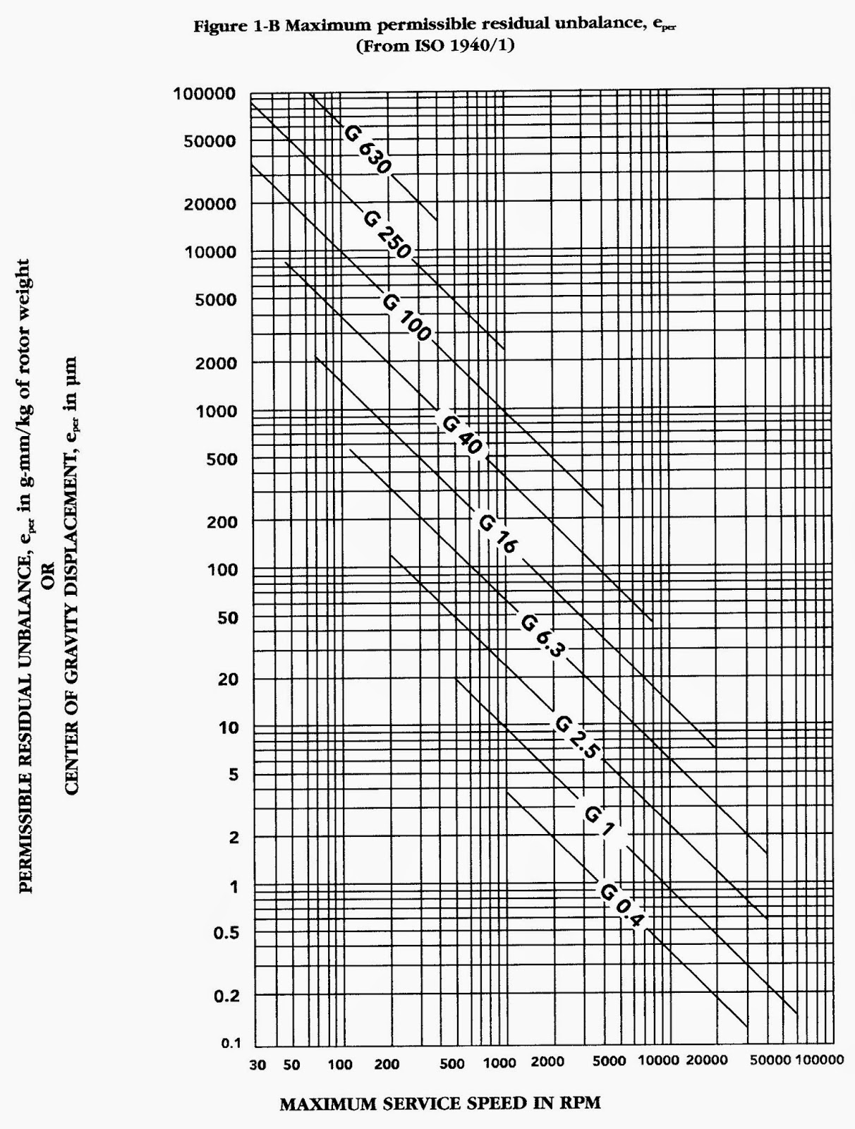
To use this standard one must know what type of rotor is to be balanced. See the Table 1for determination of the type of rotor. From this table the second thing to note is the grade. For example centrifugal pump impellers, and flywheels fall under G 6.3 grade. The steam and gas turbine rotors and turbo compressor impellers are under grade G 2.5. After selecting the grade from table 1, next step is to go to Figure 1-A or Figure 1 – B, to find the maximum permissible residual unbalance eper .
As an example, we have a centrifugal compressor rotor of weight 2200 lb. weight. The maximum operating speed is 5000 RPM. The grade as per table 1 is G2.5. Then the formula become
U per = ( G * e per * weight of rotor / 2 ) Max cont. RPM
= ( 2.5 * 6.0 * 2200 / 2 ) / 5000
= 3.3 oz-inch
If we use the formula given in API - 617, the formula is
U per = 4 W / N , where W = total rotor weight in lbs. and N = Max Continuous operation RPM. Applying this formula to the previous example, we get
U per = 4 W / N = 4 * 2200 / 5000 = 1.76 oz – inch.
Obviously API - 617 standard is more stringent, as it allows a smaller permissible unbalance of 1.76 oz-inch compared to the 3.3 oz-inch allowed by ISO -1940.
The other API standards also specify the similar things as far as dynamic balancing of the rotors is concerned. The allowable residual unbalance per plane as specified by different API standards is tabulated as follows-
S.N. | API STD . | APPLICABLE FOR | FORMULA |
1 | API 611 | Gen. Purpose Steam Turbines | U max = 4 W / N |
2 | API 616 | Gas Turbines For Refineries | U max = 4 W / N |
3 | API 6 17 | Centrifugal Compressors | U max = 4 W / N |
4 | API 610 | Centrifugal Pumps for Petroleum , gas etc | U max = 4 W / N |
Where Umax = residual unbalance in ounce-inches ( gram-millimetres in SI )
W = Journal static weight load in pounds ( kilograms in SI )
N = maximum continuous speed in revolutions per minute RPM.
The above formula for SI units is expressed as , U max = 6350 W / N
TABLE 1 : BALANCEQUALITY GRADES & THE ROTOR TYPES , ISO 1940
Balance Quality Grade | Product of E per * W | ROTOR TYPES – GENERAL EXAMPLES |
G 4000 | 4000 | Crankshafts/ drives of rigidly mounted slow ( where the piston speed is less than 9 m/s ) marine diesels with uneven number of cylinders. |
G 1600 | 1600 | Crankshafts/ drives of rigidly mounted two-cycle engines. |
G 630 | 630 | Crankshafts/ drives of rigidly mounted large four-cycle engines and Crankshafts/ drives of elastically mounted marine diesel engines. |
G 250 | 250 | Crankshafts/ drives of rigidly mounted fast( where the piston speed is more than 9 m/s ) four cycle diesel engines |
G 100 | 100 | Crankshafts/ drives of fast diesel engines with six or more cylinders. And complete engines for cars, trucks, etc |
G 40 | 40 | Car wheels, wheel rims, wheel sets, drive shafts, Crankshafts/ drives of elastically mounted fast four-cycle engines with six or more cylinders. Crankshafts/ drives of engines of cars, trucks, etc |
G 16 | 16 | Drive shafts ( propeller shafts, cordon shafts with special requirements ) , Parts of crushing machines, agricultural machinery, individual components of engines for cars, trucks, etc. |
G 6.3 | 6.3 | Parts of the process plant machines Centrifuge drums, paper machinery rolls, print rolls, fans, flywheels, assembled aircraft gas turbine rotors, , pump impellers, machine tool and general machinery parts, medium and large electric armatures, small electric armatures |
G 2.5 | 2.5 | Gas and steam turbines, rigid turbo generator rotors, turbo compressors, machine tool drives, medium and large electric armatures with special requirements, turbine driven pumps |
G 1 | 1 | Tape recorder and phonograph drives, grinding machine drives Small electric armatures with special requirements |
G 0.4 | 0.4 | Spindles, discs and armatures of precision grinders, Gyroscopes |
Note : W = 2 p N / 60 rad / sec.
SUMMARY ON API STANDARDS FOR BALANCING ASPECT : -
API 617 For Centrifugal Compressors specifies the following guidelines.
Ref. Para 2.9.5.1: - Major parts of the rotating element, such as shaft, balancing drum, and impellers shall be dynamically balanced. When a bare shaft with a single keyway is dynamically balanced, the keyway shall be filled with a fully crowned half-key. The initial balance correction to the shaft shall be recorded. A shaft with keys 180 degrees apart but not in the same transverse plane shall also be treated as described above.
Ref. para 2.9.4.3: - The rotating element shall be multiplane dynamically balanced during the assembly. His shall be accomplished after adding no more than two major components. Balancing correction shall be applied only to the elements that are added. Other components may require minor corrections during the final trim balancing of the completely assembled element. On rotors that have single keyways, the keyway shall be filled with fully crowned half-key. When specified, the weight of all half keys used during the final balancing of the assembled element shall be recorded on the residual unbalance worksheet. The maximum allowable residual unbalance per plane ( journal ) shall be calculated as follows; -
U max = 4 * W / N ( and in SI units U max = 6350 W / N )
Where Umax = residual unbalance in ounce-inches ( gram-millimetres in SI )
W = Journal static weight load in pounds ( kilograms in SI )
N = maximum continuous speed in revolutions per minute RPM.
When spare rotors are supplied they shall be dynamically balanced to the same tolerance as main rotor.
Ref. Para 2.9.5.4 – High speed balancing ( balancing in the high speed balancing machine at the operating sped ) shall be done only with the purchaser’s specific approval. The acceptance criteria for this balancing shall be mutually agreed upon by the purchaser and the vendor.
The other standards like API : 610-for pumps, API :611 – for steam turbines, API : 672 – packaged integrally geared compressors, etc also provide similar guidelines.
7 References
ISO 1940 – Balance Quality Of Rotating Rigid Bodies – classifies all rigid rotors and recommends balance tolerances for them.
API STANDARD 610 - Centrifugal Pumps For Petroleum , Heavy Duty Chemical, And Gas Industry.
API STANDARD 611- General Purpose Steam Turbines For Refinery Services.
API STANDARD 616 – Gas Turbines for Refinery Services.
API STANDARD 617 - Centrifugal Compressors For Petroleum , Chemical, and Gas Service Industry.
Machinery Component Maintenance and Repair by Heinz P Bloach & Fried K. Geitner – Gulf Publishing.
Compressors Selection & Sizing –By Royce N. Brown – Gulf Publishing Company.
Hard – Bearing Balancing Machines – SHENCK RoTec GmbH.
PGW- Turbo Compressors for the Process Industry – Pumpen- und Geblasewerk Leipzig GmbH.
↧
DC Voltage Testing of Insulation
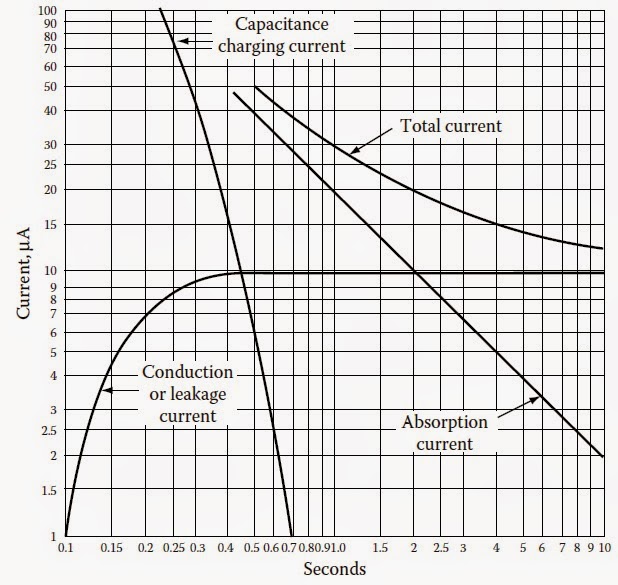
When DC voltage is applied to an insulation, the electric field stress gives rise to current conduction and electrical polarization. Consider an elementary circuit as shown in Figure 1.1, which shows a DC voltage source, a switch, and an insulation specimen. When the switch is closed, the insulation becomes electrifi ed and a very high current fl ows at the instant the switch is closed. However, this current immediately drops in value, and then decreases at a slower rate until it reaches a nearly constant value. The current drawn by the insulation may be analyzed into several components as follows:
Capacitance
• Charging current
• Dielectric absorption current
• Surface leakage current
• Partial discharge current (corona)
• Volumetric leakage current
Capacitance charging current: The capacitance charging
current is high as the DC voltage is applied and can be calculated by the formula:
Image may be NSFW.
Clik here to view.
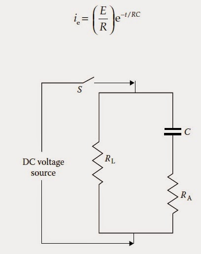
FIGURE 1.1
Electrical circuit of insulation under DC voltage test.
where
ie is the capacitance charging current
E is the voltage in kilovolts
R is the resistance in megohms
C is the capacitance in microfarads
t is the time in seconds
e is Napierian logarithmic base
The charging current is a function of time and will decrease as the time of the application of voltage increases. It is the initial charging current when voltage is applied and therefore not of any value for test evaluation. Test readings should not be taken until this current has decreased to a sufficiently low value.
Dielectric absorption current: The dielectric absorption current is also high as the test voltage is applied and decreases as the voltage application time increases, but at a slower rate than the capacitance charging current. This current is not as high as the capacitance charging current. The absorption current can be divided into two currents called reversible and irreversible charging currents. Thisreversible charging current can be calculated by the formula:Image may be NSFW.
Clik here to view.

where
ia is the dielectric absorption current
V is the test voltage in kilovolts
C is the capacitance in microfarads
D is the proportionately constant
T is the time in seconds
n is a constant
The irreversible charging current is of the same general form as the reversible charging current, but is much smaller in magnitude. The irreversible charging current is lost in the insulation and thus is not recoverable. Again, sufficient time should be allowed before recording test data so that the reversible absorption current has decreased to a low value. be eliminated by the use of stress control shielding at such points during tests.
Surface leakage: The surface leakage current is due to the conduction on the surface of the insulation where the conductor emerges and points of ground potential. This current is not desired in the test results and should therefore be eliminated by carefully cleaning the surface of the conductor to eliminate the leakage paths, or should be captured and guarded out of the meter reading.
Partial discharge current: The partial discharge current, also known as corona current, is caused by overstressing of air at sharp corners of the conductor due to high test voltage. This current is not desirable and should be eliminated by the use of stress control shielding at such points during tests. This current does not occur at lower voltages (below 4000 volts), such as insulation resistance test voltages.
Volumetric leakage current: The volumetric leakage current that flows through the insulation volume itself is of primary importance. This is the current that is used to evaluate the conditions of the insulation system under test.
Sufficient time should be allowed for the volumetric current to stabilize before test readings are recorded. The total current, consisting of various leakage currents as described above, is shown in Figure 1.2.
Figure 1.2:
Various leakage currents due to the application of DC high voltage to an insulation system.
↧
↧
Reliability Of Rotating Equipment By Vibration Monitoring
Reliability Of Rotating Equipment By Vibration Monitoring |
To give an overall idea to the Maintenance Personnel about the Predictive Maintenance Programme / Reliability & Condition Monitoring Concepts, Principles and Techniques.
This Manual is intended to explain in general about different types of condition monitoring techniques, analysis and diagnostics on any type of rotating equipment.
1 Introduction
1.1 Predictive maintenance concepts and objectives
1.2 Vibration and its causes
2 VIBRATION MEASUREMENT TYPES
2.1 Vibration Displacement
2.2 Vibration Velocity
2.3 Vibration Acceleration: (Figure-1)
2.4 Vibration Frequency
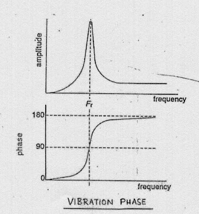
2.5 Vibration Phase: (Figure-2)
2.6 Acoustic emission and Shock pulse
3 transducer types
3.1 Contact type:(Figure-3)
3.1.1 ELECTRO MAGNETIC/VELOCITY PROBES:
3.1.2 PIEZO-ELECTRIC/ACCELEROMETER PROBES:
3.2 Non-contact type
3.2.1 EDDY CURRENT/PROXIMITY PROBES
3.3 Transducer selection
4 Monitoring TYPES
4.1 On-line monitoring:
Figure-6*
4.2 Off-line or periodic monitoring
5 vibration analysis and machinery diagnostics
5.1 Types of Vibration Plots
5.1.1 TREND PLOT : (Figure-11)
5.1.2 SPECTRUM PLOT: (Figure-12&13)
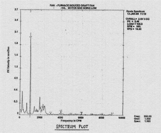
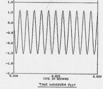
5.1.3 TIME WAVEFORM PLOT: (Figure-14)
5.1.4 WATERFALL PLOT: (Figure-15)
5.1.5 CASCADE PLOT:(Figure-16)
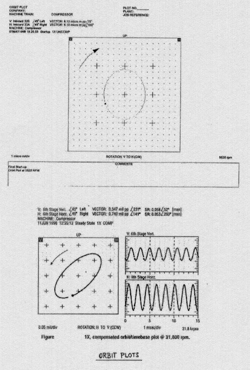
5.1.6 ORBIT PLOT:(Figure-17)
5.1.7 BODE PLOT:(Figure-18)
5.1.8 POLAR PLOT:(Figure-19)
5.1.9 CENTER LINE PLOT
5.2 Typical problems and Diagnostics
6 Vibration standards
1.1 Predictive maintenance concepts and objectives
In recent years industry has started to realise the financial benefits and engineering improvements created by utilising Predictive Maintenance techniques.These techniques can give advanced warning of any impending mechanical or any other machinery/structural related problems allowing them to be rectified in a planned manner thus improving the machinery reliability. Problems are diagnosed in advance or at an early stage itself to avoid any unexpected machine breakdown thus avoiding plant downtime.
Various techniques like Vibration monitoring,Process monitoring,Lube oil analysis are used in Predictive maintenance programs out of which Vibration Monitoring is considered to be a widely used and proven technique.
The objective of machinery monitoring is to increase the availability and reliability of machinery and decrease the maintenance costs by:
· Preventing catastrophic failures
· Detecting machinery distress to allow corrective action before major damage occurs
· Reducing spareparts requirements
· Improving operation and maintenance by providing better knowledge of machinery rotor and bearing behaviour
· Prolonging the periods between machinery major overhauls by providing better insight into the condition of machinery in operation
· Providing information for correction of basic design deficiencies
· Reducing the downtime by detecting the onset of a problem,enabling remedial repairs to be made during scheduled outages
· Predicting maintenance requirements,allowing advanced scheduling and planning of maintenance work
1.2 Vibration and its causes
Vibration is the motion of a machine or part of a machine to and from its position of rest.
The cause of vibration must be a force which is varying in either its direction or its amount.It is the force which causes vibration and the resulting characteristics will be determined by the manner in which the forces are generated.That is why each cause of vibration has its own specific characteristics.
With few exceptions, mechanical problems in a machine cause vibration.Some of the common problems which produce vibration are:
· Unbalance of rotating parts
· Misalignment of couplings and bearings
· Worn or damaged bearings
· Bent shafts
· Looseness
· Rubbing
· Machine/structural resonance
· Worn,eccentric or damaged gears
· Aerodynamic/Hydraulic forces
2 VIBRATION MEASUREMENT TYPES
The displacement,velocity and acceleration are the three characteristics of vibration by which the vibration amplitude is quantified (Refer figure 1).In terms of the operation of a machine, the vibration amplitude is the indicator used to determine the condition of the machine.Types of measurement differs from machine to machine mostly depending upon the machine type and bearing type.Vibration monitoring and machinery diagnostics gives good results only when right type of measurement is chosen for the machines. Common types of measurements done with rotating machinery are,
· Relative shaft vibration -- using non-contact type pickups
· Absolute casing vibration -- using contact type pickups
2.1 Vibration Displacement:
The total distance travelled by the vibrating body from one extreme limit of travel to the other extreme limit of travel is referred to as the “peak to peak displacement” and mostly measured in “microns” or in “mils” (peak,peak-to-peak or rms).
This type of measurement is chosen when a machine has a low rotor- to-casing mass ratio i.e the rotating parts are much lighter than the stationary parts(casings, bearing housings etc.).There is much less energy(vibration)to measure on the casing and it is more important to measure the actual movement of the shaft within its bearings. A good example of a machine with low rotor-to-casing mass ratio is a barrel type compressor.
2.2 Vibration Velocity:
The velocity at which the vibrating body covers the displacement is referred to as “vibration velocity” and mostly measured in “mm/sec” or in “inch/sec” (peak or rms).
Velocity is the most widely used parameter in vibration measurement.This is due to equal weighting of velocity amplitude through a wide frequency range, thus allowing to identify a wide range of problems.The International Standards Organisation (ISO), in its work to establish internationally acceptable units for measurement of machinery vibration, decided to adopt “vibration velocity”as the standard unit of measurement. Vibration velocity is mostly measured on machines with low casing-to-rotor mass ratio like pumps,blowers,fans,reciprocating compressors etc..
2.3 Vibration Acceleration:(Figure-1)
Acceleration is normally referred to as time rate of change of velocity and measured in “G’s” (peak) where one “G” is the acceleration produced by the force of gravity (1G’s=9.8m/sec2).
Figure:1
Acceleration leads velocity by 90 degrees in time, and leads displacement by 180 degrees in time.
Acceleration amplitudes are weighted towards the higher frequency ranges and as a result, it can give a better indication of incipient anti-friction bearing problems,gear tooth meshing problems and high speed machinery problems.
2.4 Vibration Frequency:
Frequency is usually expressed in Hertz(Hz) or cycles per minute(CPM).Frequency is also often quoted in multiples of rotating speed of the machine train, this is because most machinery vibrations occur in direct multiples or sub-multiples of rotating speed.It also provides an easy means to express the frequency of vibration, it being easier to refer to frequency as once times rpm(1X),two times rpm(2X) and so on rather than having to express all vibration in cpm or Hertz.Frequency is probably the most important characteristic of vibration as it indicates the probable source of vibration.
Machines can simultaneously generate a number of frequencies relative to the various forces which are acting and reacting in the machine and it is necessary at times to know what the dominant frequency of a particular machine is, if we are measuring overall levels.
2.5 Vibration Phase: (Figure-2)
Accurate diagnosis of machinery problems requires a complete set of machine vibration information.That information comes from the three primary parts of the data that we can obtain from a vibration signal, like direct amplitude, frequency and when, there are two signals, phase (Refer figure 2). Relative phase is the timing relationship between two vibration signals, while absolute phase compares a vibration signal to a once-per-turn reference pulse.The keyphasor is a once-per-turn voltage pulse provided by a proximity type transducer and the information is called as phase. The keyphasor signal is used by monitoring,diagnostic and management systems to generate filtered vibration amplitude, phase lag, speed and a variety of other information.Without phase
information,overall machine condition and machine faults would often be very difficult to diagnose.
Phase information can be used to detect subtle changes to the machinery that otherwise go unnoticed. Listed below are a few of the many phase angle applications:
· Direction of vibration
· Shaft crack detection
· Rub detection
· Shaft balancing
· Shaft / structural resonance detection
· Shaft mode shape
Trending amplitude and phase information can provide early shaft crack detection and alert the operators to other possible machine problems.Rub conditions can be detected with the use of phase presented in steady state polar plots.Machinery specialists use phase extensively in their analysis to confirm suspected machine problems.
Figure:2
2.6 Acoustic emission and Shock pulse
Acoustic emissions and shock pulse methods(SPM) of monitoring anti-friction bearings are basically similar techniques, in that both use crystal or piezoelectric type transducers that measure stressed bearing activity in a frequency range between 35 KHz to 50 KHz.The transducer mounted natural frequency is also in this frequency range and typically has low damping.This gives an effective amplification of the signal and defects can be detected earlier.
The term acoutic emission is applied to the so-called shock pulse which is emitted by a material under stress.The pulse is generated in the material and into the adjacent structure.In a ball or roller bearing this pulse is generated when, for example, a crack occurs in an inner or outer race.Each time a ball or roller crosses the crack ,it is stressed, and a pulse is generated in the ball or the race and transmitted through the race into the mounting structure.
The pulse has a very high energy content for a very short time.The frequency of this signal is well above the normal bearing vibration range.It is in the band of frequencies centered about 40,000 Hz.The pulses occur at a rate directly related to the number of balls and rotational speed of the bearing.
The acoustic emissions are in a frequency range distincly different from sounds produced as a result of vibration of the bearing or its mounting structure.These latter vibrations occur at much lower frequencies and over a wide range dependent on the speed of rotation,resonances of the structure etc,.. Vibration frequencies range from about 20 Hz to 15 Khz for shaft speeds of up to 100,000 rpm.It should also be noted that acoustic emission occurs long before vibration is measurable.If vibration is in evidence,the bearing has long since started to fail.
3 transducer types
To measure vibration, a transducer or vibration pickup is needed to convert the mechanical motion into an equivalent electrical signal. There are two major classification of transducer types:
· Contact type
· Non-contact type
3.1 Contact type:(Figure-3)
This class of transducers are used for casing vibration measurements mostly velocity and acceleration (Refer figure 3). These type of probes can be mounted as follows:
· Stud mounting
· Magnetic mounting
· Hand held probe
The method of mounting of the transducer will affect the useful frequency range of the transducer. There are certain advantages and disadvantages in these type of probes.
Figure:3
3.1.1 ELECTRO MAGNETIC/VELOCITY PROBES:
The velocity type transducer is a moving coil or magnetic seismic device.When a conductor is moved through a magnetic field or if a magnetic field is moved past a conductor a voltage will be induced.Either the magnet or the coil of the pickup are mounted on the machine bearing housing, the moving element is held suspended by low stiffness springs.When the bearing housing vibrates the fixed section of the transducer moves relative to the floating section and hence a voltage is generated in the coil which is directly proportional to the velocity of the vibration.
The voltage output of a velocity transducer is normally expressed in mv/mm/sec.This is also referred to as the sensitivity of the vibration pickup.Velocity probes has got the limitations like,
· Limited frequency range i.e 10-1000Hz
· Direction oriented i.e horizontal or vertical
3.1.2 PIEZO-ELECTRIC/ACCELEROMETER PROBES:
An accelerometer uses a piezo-electric crystal that produces an electrical charge directly proportional to strain (and hence force) when loaded either in tension,compression,shear.
When the accelerometer is subjected to vibration the mass exerts a varying force on the piezo-electric crystal which produces a charge directly proportional to the vibration acceleration.The charge is then converted into a voltage signal.The conversion is done internally inside the probe by an in-built charge amplifier.
Their output voltage is proportional to vibration amplitude and the square of the frequency. The normal sensitivity range is in the range of 100mv/g.
Accelerometers are widely used as compared to electromagnetic type because of its own advantages like,
· Better frequency response characteristics (dc-0 Hz to typically 20 KHz)
· No mounting orientation restrictions
· Extended temperature ranges
· Compact and light weight
· No moving parts and hence rare failures
· Available at very low frequency to high temperature ranges for different applications
3.2 Non-contact type
This type of probes are widely used for relative shaft displacement measurement on critical compressors. Non-contact type pickup is a transducer used for vibration and position measurement that doesn’t require contact with the target whose vibration or position being measured.This type of probe works on eddy-current principle.
3.2.1 EDDY CURRENT/PROXIMITY PROBES:
Shaft vibration,radial and axial shaft movement, shaft and housing expansion can all be measured using non-contact type displacement pickups (Refer figure 4). Eddy current is referred as the electrical current which is generated (and dissipated) in a conductive material when such material intercepts the electromagnetic field of a proximity probe.The proximity/eddy current probe is powered by the instrument/monitor.The probe is driven by a high frequency carrier signal and whenever the target moves , the carrier signal is altered which is sensed by the de-modulator and a proportional voltage output is generated corresponding to the peak-to-peak vibration displacement of the target(shaft).The probe measures both dynamic motion and average position of the shaft with a good frequency response. The probe gap is the physical distance between the face of a proximity probe tip and the observed surface. The distance can be expressed in terms of displacement(mils,micrometers) or in term of voltage(volts).
The normal working frequency range is dc 0-10000Hz with a displacement measuring range of 2mm. Nominal sensitivity is in the range of 8mv/micron(200mv/mil)
Figure-4
3.3 Transducer selection
Transducer selection for a particular machine depends on the machine type,bearing type and the type of measurement required.
Shaft observing eddy-current proximity probes directly measure the relative displacement between the probe and the conductive surface it observes,generally a rotating or reciprocating machinery shaft.These transducers are extremely sensitive and accurate in measuring displacements in the order of micrometers.These probes directly observe the relative shaft motion inside the bearing clearances of fluid film bearings.These bearings are employed in the majority of large,high speed turbomachinery and proximity probes are permanently mounted on these machine types for continuous on-line monitoring.
Casing observing transducers include both velocity transducers and accelerometers.As the name implies, they are both used to measure casing motion and are mounted temporarily or permanently on the machine or bearing housing.These type of probes cannot be used directly to observe rotor motion within the bearing clearances.Therefore, their usefulness as the primary or only measurement on machines incorporating fluid-film bearings is normally not appropriate.The proper application of these transducers requires detailed knowledge of their limitations and the effects of signal conditioning such as integration and filtering.
4 MOniTORING TYPES
Two types of vibration monitoring techniques are widely used worldwide.They are
· On-line monitoring (Continuous/Permanent)
· Off-line monitoring (Periodic/Temporary)
The scope, extent and type of monitoring, modified by operating experience, judgement and economic analysis should be based on whether it is:
· A critical unspared machine
· A critical or possible failure prone machines
· A critical spared machine in light service
· A non-critical unspared machine
· A non-critical spared machine
4.1 On-line monitoring:
Continuous collection of vibration data by means of permanent monitoring systems is called as on-line monitoring (Refer figure 5 to 9 for such typical systems).Dedicated on-line systems with diagnostic capabilities makes it possible to make timely decisions regarding machinery health that can be used to better schedule of maintenance,delay shutdowns,thus eliminating any unscheduled outages as well as preventing catastropic failures.Various systems with different capabilities are available in the market. Most of the process critical machineries like compressors, gear boxes, high pressure steam turbines, expander turbines, large electric motors, boiler feed water pumps are monitored by permanently installed non-contact type proximity probes. In
certain hazardous area locations with limited access,accelerometers are also permanently mounted on pumps for on-line continuous vibration monitoring.
A typical on-line monitoring system consists of either a non-contact proximity or accelerometer type probes connected to the Data management software work station through rack mounted signal transmitters and communication processors. Work stations with Data management software is usually located in control room or in engineer’s office whereas rest of the hardware is field mounted.The latest systems are capable of collecting data in steady-state and also in startup/shutdown(transient) operating conditions.
This type of monitoring is most suitable for critical/super critical machineries since continuous vibration monitoring of those machines are inevitable due to their process importance. Any increasing vibration trend can be noticed immediately and further action can be taken to avoid any unexpected plant shutdown and production losses. Maintenance activities can be planned in advance to avoid any prolonged shutdown due to non-availability of spares,manpower etc.,if any.
Another advantage of on-line monitoring is its capability to correlate vibration data with process parameters. Process data like pressure, flow, temperature can always be related with vibration data under two different operating conditions especially for process critical compressors for better performance analysis and reliability studies.
The major parameters monitored by this on-line monitoring includes,
· Radial relative shaft vibration
· Axial thrust position (Average position, or change in position, of a rotor in the axial direction with respect to some fixed reference)
· Speed / Phase angle
· Torque
Figure-5
Figure-6
Figure-7
Figure-8
Figure-9
4.2 Off-line or periodic monitoring
Vibration data collection of machineries at certain time intervals using portable data collection systems is called as Off-line or Periodic vibration monitoring (Refer figure 10). Most of the non-critical / critical machineries like utility pumps, blowers, fans, small motors etc., fall under this category of monitoring.
A typical off-line or periodic monitoring system consists of a data collector with contact type accelerometers used in conjunction with a data collection software loaded into a PC. Most of the data collected with this type of monitoring are by casing vibration measurement in three different directions (horizontal / vertical / axial) at bearing locations.Measurement points are downloaded from the PC software in to the datacollector as per monthly / biweekly schedules for data collection. Once the route data collection is completed, data is uploaded in to the PC software for further analysis and diagnostics.
Figure-10
5 vibration analysis and machinery diagnostics
There are many ways that vibration data can be obtained and displayed for the purpose of detecting and identifying specific problems in rotating machinery.Some of the common techniques include:
· Amplitude vs frequency (RPM) - Spectrum
· Amplitude vs time - Waveform
· Amplitude vs frequency vs time - Waterfall
· Amplitude/phase vs rpm - Bode plot
· Orbits
· Shaft center line plots
Vibration signals measured on machineries are mostly complex.This signal consists of a number of signals of different frequencies and amplitudes.From this signal it would be difficult to abstract the different amplitudes and frequencies of vibration which exist within signal.The signal can be processed electronically into what is known as a vibration spectrum, fast fourier (FFT)spectrum or a frequency spectrum.The vibration spectrum gives a breakdown of the different vibration frequencies and their amplitudes which exist within the original vibration signal.
The identification of the vibration signal’s frequencies(source) and the amplitudes(severity) for a machine holds the key to the use of vibration to assess the machine’s condition.
When interpreting vibration data we have to identify two things:
· The levels of vibration i.e vibration severity and whether they aregood,acceptable or unacceptable.
· The source of vibration
Various standards organisations like ISO/API have produced guidelines on the assessment of machinery vibration levels. But it is to be noted that complete assessment is done only after studying the individual characteristics of the machine.
5.1 Types of Vibration Plots
5.1.1 TREND PLOT : (Figure-11)
A presentation in cartesian format with the measured variable (like vibration amplitude) on the Y axis and time on the X axis.
Figure-11
5.1.2 SPECTRUM PLOT: (Figure-12&13)
Presentation of the amplitude of a signal as a function of frequency. An XY plot where the X axis represents vibration frequency and the Y axis represents vibration amplitude.
Figure-13
5.1.3 TIME WAVEFORM PLOT: (Figure-14)
A presentation of the instantaneous amplitude of a signal as a function of time. A vibration waveform can be observed on an oscilloscope in the time domain.
5.1.4 WATERFALL PLOT: (Figure-15)
A graph in cartesian format displaying a series of frequency spectra versus time. This type of plots are useful in comparison of spectrums collected at different time intervals mostly with same rotative speed.
Figure-14
Figure-15
5.1.5 CASCADE PLOT:(Figure-16)
A graph in cartesian format displaying a series of frequency spectra versus shaft rorative speed. This XYY’ presentation shows amplitude (Y) versus frequency (X) incremented along a second (sometimes vertically offset) Y axis , rpm. This data format is used to evaluate the change in vibration frequency characteristics during machine transient conditions like startups/coast down.
Figure-16
5.1.6 ORBIT PLOT:(Figure-17)
The dynamic path of the shaft centerline displacement motion as it vibrates during shaft rotation. The orbit can be observed on an oscilloscope connected to XY proximity probes.Sometimes called precessional motion or orbital motion.
Figure-17
5.1.7 BODE PLOT:(Figure-18)
The Bode plot is two separate cartesian plots of amplitude versus rpm and phase lag versus rpm. Rotative machine response has usually been measured through the use of the Bode plot, a technique used to plot rotative speed amplitude (1X) of a given measurement against rpm, along with the phase lag angle of that amplitude vector against rpm. This plot most useful in showing the rpm of variuos resonances of the machine.
5.1.8 POLAR PLOT:(Figure-19)
The Polar plot is a combination of three variables (amplitude, phase, rpm) into a single plot in a circular format. Polar plot is much descriptive and useful to the machinery engineer in displaying other parameters of machine response.
Figuare-18
Figure-19
5.1.9 CENTER LINE PLOT
The Shaft center line plot is a plot in circular format with two variables i.e vibration amplitude and rotative speed. It gives a very useful machinery information of radial shaft movement inside the bearing clearances at different running speeds.
5.2 Typical problems and Diagnostics
The following table illustrates the typical or most common problems,their symptoms and diagnostics.
CAUSE / PROBLEMS | FREQUENCY | AMPLITUDE | REMARKS |
Unbalance | 1 X RPM | Proportional to unbalance. Largest in radial direction | Most common cause of vibration. |
Misalignment Couplings or bearings and bent shaft | 1 X RPM usual 2 X, 3 X RPM sometimes | Large in axial Direction. 50% or More of radial vibration | Best found by appearance of large axial vibration.If sleeve bearing machine and no coupling misalignment then balance the rotor. |
Bad bearings Anti-friction type | Very high. several times RPM | Unsteady | Largest high frequency vibration with associated noise. Special techniques like SPM / SEE / Enveloping can be adopted. |
Bad gears or Gear noise | Very high. Gear teeth times RPM | Low | Usually accompanied by high temperature and noise. |
Mechanical looseness | 2 X RPM and hormonics | Usually accompanied by unbalance and /or misalignment. | |
Bad drive belts | 1 X, 2 X, 3X RPM of belts | Erratic or pulsing | Strobe light can be used to freeze faulty belts. |
Electrical | 1 X RPM or 1 or 2X synchronous frequency | Disappears when power is switched off | If vibration amplitude drops down instantly when power is turned off, the cause is electrical. |
Aerodynamic Hydraulic forces | 1 X RPM or number of blades on fan or impeller X RPM | Moderate & steady | Rare as a cause of trouble except in cases of resonance. |
Reciprocating forces | 1, 2 & higher orders X RPM | High & steady | Inherent in reciprocating machines. Can only be reduced by design changes or isolation. |
6 Vibration standards
Various international organisations have developed standards for different type of rotating equipment. Mostly these standards are considered as guidelines only in detemining the machine condition since individual machineries have their own characteristics which will be used in arriving at the final conclusion of machine condition detemination.
The most common vibration standards used nowadays are:
· International Standards Organisation (ISO)
· American Petroleum Institude (API)
· National Electrical Manufacturer’s Association (NEMA)
Image may be NSFW.
Clik here to view.![]()
Clik here to view.
Image may be NSFW.
Clik here to view.![]() CLASS 3:Large machines on rigid CLASS 4:Large machines on flexible
CLASS 3:Large machines on rigid CLASS 4:Large machines on flexible
Clik here to view.
 CLASS 3:Large machines on rigid CLASS 4:Large machines on flexible
Foundations (steam turbines, foundations (large turbo-generators, large centrifugal compressors) fans, blowers)
Image may be NSFW.
Clik here to view.![]() Image may be NSFW.
Image may be NSFW.
Clik here to view.![]()
Clik here to view.
 Image may be NSFW.
Clik here to view.
API 610 : Centrifugal pumps for general refinery service
· Pumps with sleeve bearings
RPM Shaft vibration
Image may be NSFW.Clik here to view.
· Pumps with anti-friction bearings
Image may be NSFW.Clik here to view.
API 611 : General purpose steam turbines
Clik here to view.
API 612 : Special purpose steam turbines
Image may be NSFW.
Clik here to view.

API 613 : Special purpose gears
API 617 : Centrifugal compressors
API 672 : Centrifugal plant and instrument air compressors
API RP541 : Electric motors
RPM Casing vibration
720 to 1499 <2 .5="" font="" mils="" pp="">2>
1500 to 2999 <2 .0="" font="" mils="" pp="">2>
>3000 <1 .0="" font="" mils="" pp="">1>
↧
Radiant Coil Repair Procedure in Cracking Furnaces
Radiant Coil Repair Procedure in Cracking Furnaces] |
This procedure applies to Cracking Furnaces ( 11-FH-201/205)
Contents.
1 Terminology
2 EQUIPMENT NAME (SERVICE)
3 TAG NUMBER OF EQUIPMENT
4 RESPONSIBILITIES
5 SAFETY, HEALTH & ENVIRONMENT PRECAUTIONS
5.1 PROTECTIVE EQUIPMENT
6 MATERIAL NEEDED
7 TOOL LIST
8 MAINTENANCE PROCEDURE
9 CHECK LIS
10 DEVIATIONS FROM PROCEDURE
11 SUGGESTION FOR improvement
12 References & Attachments
1.0 TERMINOLOGY:
Key terminology used in this document is either defined on its first occurrence or takes the common definition as stated in the;
1.1 WPS: Welding Procedure specification.
1.2 ID Fan: Induced Draft Fan
1.3 DM Water: Demineralized Water
2.0 Equipment Name:
CrackingFurnace Radiant Coils
3.0 Tag Number of equipment:
Radiant Coils for Furnace 11-FH-201/205
4.0 Responsibilities:
1. Shift Supervisor( Operations)- For making system ready for maintenance.
2. Maintenance Supervisor: For Job execution and Job planning before the start of the job and history Updating.
3.Maintenance Technician: To follow work instruction and time logging.
4.Maintenance Engineer: To ensure the availability of the procedure for the job.
5.0 Safety and Environmental Precausions:
5.1 The radiant coils will become very brittle in nature in aged condition. Hence the coils need to be supported at several places if coils are to be cut for maintenance.
5.2 The location of joint has to be decided keeping in view of the safety of the persons working and welder convenience. If possible the joint to be made at floor level.
5.3 When persons are working in the fire box, ensure that radiant coils are not blown with Nitrogen.
5.4 Ensure that ID Fan is running and firebox is sufficiently ventilated.
5.5 Only 24 Volts hand lamps should be used in side the firebox.
5.6 All the hydrocarbon lines are to that Furnace to be positively blinded.
5.7 Scaffolding/ Platforms to be arranged as per standards.
5.8 Fire box manholes on both sides to be opened for persons to enter into the firebox.
5.9 Before cutting the coils, ensure that they are supported at as many locations as possible with the help of chain blocks, nylon ropes.
5.1 Personal Protective equipment to be used:
- Hard hat
- Eye protection
- Safety belt for the welder
- Safety shoe
- Dust mask
- Disposable Coveralls
6.0 Materials Needed:
- Filler wires as per the “WPS”
- Scaffolding material.
7.0 Tools required:
1.Chain Blocks( 1 or 2 Tons capacity)
2. Nylon rope
3. TIG- welding set with necessary filler wires( See attachments for Details)
4. Clamps for fit up.
5. Thermo chalks
6. Boroscope to check inside the coil
7. Hydrojetting machine if the coils need dechocking.
8.0 Maintenance Procedure :
8.1 The following permits to be obtained from Operations department for radiant coils repair job:
1. Cold work Permit.
2. Hot Work permit.
3. Confined space entry permit
8.2 Cutting / Edge preparation and Rewelding:
1. The orientation markings to be made before cutting the coils. Otherwise the fit up will be proper as they have bow.
2. Ensure that nitrogen pressure is not there in the coils before cutting and minimum thickness of the cut off wheel should be used to part the coil.
3. The coil parts are to be taken out of the fire box for dechocking by hydrojetting.
4. Ensure that the markings made on the coil with crayons do not contain sulfur.
5. See the attached WPS for the details related to the edge preparation, filler wire specification, and Procedure.
6. Ensure that interpass temperature does not go beyond 150 Deg C.
7. For rewelding, the clamps can be used for proper fitup and Tack welding. Ensure the sufficient inert gas flow inside the coil.
In this case ,the pure Dry nitrogen from utility header can be used. Ensure that ID Fan is running and maximum air is sucked through the fire box in which welding is to be carried out. Keep monitoring the oxygen level at the work place continuosly and masking tape is to be used to minimise the nitrogen coming in to the fire box during welding. The persons involved in this needs to be given tool box talk accordingly.During execution of the welding when nitrogen is used for purging portable Oxygen alarm to be used. A radio communication has to be established between welder and the Operator who has to immediately close the nitrogen valve in case of unacceptable nitrogen concentrations in the work place.
8.3 WPS :
For WPS( Welding procedure Specification) See attached WPS by the supplier of the coils” Paralloy Limited”
8.5 Inspection:
1.Inspection will be as per “ WPS”
2.Pneumatic Test to be done before taking coils into line.
3.All fit up markings to be removed or to be cleaned with some solvent.
8.6 Normalizing the system:
1. All blinds to be normalised.
2. Leak checking to be done for all disturbed flanges at operating pressure.
3. Work permits to be closed and returned to Operation Department
4. All high temperature flanges are to be hot bolted when furnace being brought up.
9.0 Check lists : NA.
10.0 Deviations from Procedure
Deviations from the requirements of this procedure are not permitted without a written waiver formally authorized and recorded in accordance with the “Incident Reporting” procedure.
11.0Suggestions FOR IMPROVEMENT
Employee contribution to the effectiveness of the way Borouge conducts its business is welcomed. Any employee of Borouge may suggest changes / revisions to this procedure by completing a “Request for Improvement” form as per the “Incident Reporting” procedure.
Request for Improvement” form as per the “Incident Reporting” procedure.
12.0Reference and Attachments:
WPS by the supplier” Paralloy Limited”
↧
Insulation Temperature Ratings
An insulation system is an assembly of insulating materials in association with the conductors and supporting structural parts of an electrical equipment and apparatus. Insulation systems for electrical equipment may be classified as solid, liquid, air and vacuum, and gases. The liquid insulation system comprise of mineral oil, silicone, and other less-flammable fluids. The gas that is primarily used for electrical insulation is SF6 gas known as sulfur hexafluoride gas.
The air and vacuum insulation system has been used from the very beginning and its characteristics are well documented and understood.
The ability of insulating materials or an insulation system to perform its intended function is impacted by other aging factors. The major aging factors are electrical stresses, mechanical stresses, environmental stresses, and thermal stresses. Mechanical stresses imposed upon the system and its supporting structure by vibration and differential thermal expansion may become of increasing importance as the size of the apparatus increases. Electrical stresses will be more significant with high-voltage apparatus or with equipment exposed to voltage transients. Environmental stresses will have an impact depending on the presence of moisture, dirt, chemicals, radiation, or other contaminants. Thermal stresses depend upon environmental conditions (high ambient), loading, and ability to dissipate heat. All such factors should be taken into account when selecting insulating materials and/or insulation systems. To help the user, IEEE Standard 1-2001, “IEEE recommended practice—General principles for temperature limits in the rating of electrical equipment and for the evaluation of electrical insulation,” has established the temperature rating for solid insulation systems of electrical equipment and apparatus. The IEEE Standard 1-2001 takes into account these factors in establishing the standards of temperature limits for particular classes of apparatus. Thus, for temperature rating purposes insulation systems are divided into classes according to the thermal endurance of the system.
According to IEEE Standard 1-2000, insulation system classes may be designated by letters and may be defined as assemblies of electrical insulating materials in association with equipment parts. These systems may be assigned temperature rating based on service experience or on an accepted test procedure that can demonstrate an equivalent life expectancy. The thermal classification of electrical insulating systems established by IEEE Standard 1-2000 is given in Table.
↧
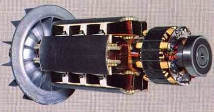


%2Bmotor.jpg)


%2BParallel-plate%2Bair%2Bcapacitor%2Band%2B(b)%2Bparallel-plate%2Bcapacitor%2Bwith%2Bdielectric%2Bmaterial..jpg)

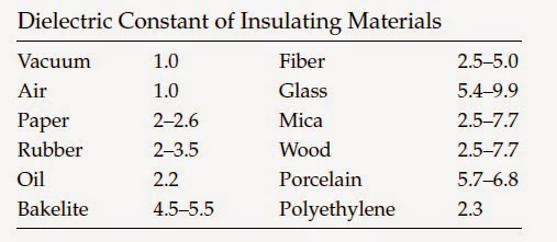
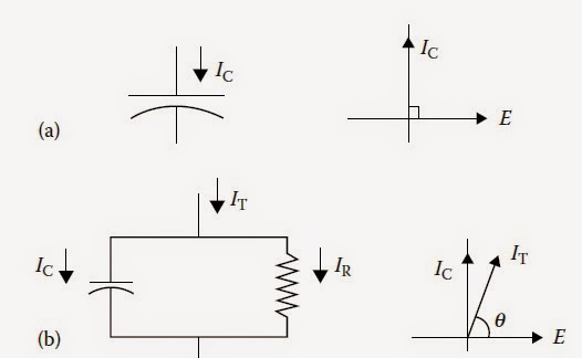%2Bperfect%2Band%2B(b)%2Bpractical..jpg)
