↧
Installation Instructions of Hydraulic Drive Motor Kit
↧
Siemens Alignment Training – Use of Laser alignment equipment Course
↧
↧
450 HP motor winding repair
↧
Reinsulation of 18.8 MW Generator
↧
A random wound stator damaged by contact with the rotor.
↧
↧
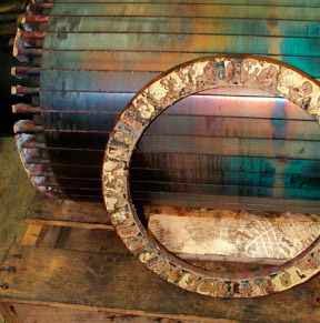
This rotor end ring was not properly brazed to the bars, resulting in a complete open circuit failure.
↧
DC Induction Motor (Reprinted with permission from LEESON electric, a subsidiary of Regal-Beloit Corporation)
↧
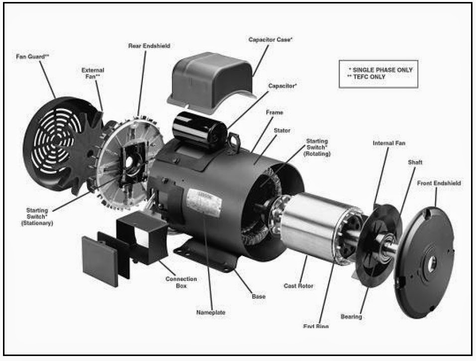
Single Phase AC Motor (Courtesy of Leeson Electric, a Subsidiary of Regal-Beloit Corporation).
↧
Optimising new electric motor designs
26/6/2013
![Comparison of conventional (a) and concentrated (b) windings (Photo: Universität der Bundeswehr)]()
- Comparison of conventional (a) and concentrated (b) windings (Photo: Universität der Bundeswehr)
Yokogawa power analysers are playing a key part in tests designed to optimise the efficiency of a new generation of motors for electric vehicles being developed by German drives specialist FEAAM in co-operation with the Institute for Electrical Drives & Actuators of the Universität der Bundeswehr (University of the Federal Armed Forces) in Neubiberg, near Munich.
The new motors are being developed as part of a research project to examine ways of increasing the efficiency of induction motors with the aim of challenging two perceived limitations that are hampering the market acceptance of electric cars: namely, the short range and the high purchase price. The research project is looking at the components of the drive train, and is basing its tests on driving cycles: the same concept that is used in efficiency and emissions tests on internal combustion engines. An important element of this approach is that the results do not depend on the efficiency at maximum load conditions, but on the efficiency at partial load operation.
Single-tooth winding
A promising approach for the optimisation of the electric motor efficiency is the concept of asynchronous motors with concentrated windings. Unlike a conventional induction motor with distributed winding, where the coils are wound around multiple lamination teeth, the windings use only a single tooth. Although this technique has been known about for some time, it has not previously been practically applied because of the interfering harmonics that can occur.
In the joint research project, FEAAM and the university team analysed the magnetic fields in the motor very precisely by a combination of simulation and practical experiments. As a result, they were able to devise various measures to suppress unwanted harmonics. The closer these harmonics are to the working wave, the more they can interfere with the motor's operation, causing electrical losses or acoustic noise.
The damping of the harmonics is achieved by a special winding technique in which adjacent tooth coils are wound in opposing directions. With the correct configuration of the number of wires in each coil, the harmonics can be reduced. In the research project, the structure of the coils is first simulated using mathematical models, and the effects are then verified by measurements.
At the test bench
The University's Institute for Electrical Drives & Actuators has several test facilities for electric motors with an output of up to 220 kW and a peak torque of 2000 Nm. The test benches are designed for four-quadrant operation, and are equipped with high-precision speed and torque-measuring devices, power analysers and oscilloscopes. They are used for student projects as well as research and collaborative work with industry.
The development process took about two years, and has also pursued the aims of simultaneous optimisation of ease of manufacturing, low production costs and achieving a high efficiency at partial load conditions.
Prototype unit
The end result is of interest for the automotive industry and other industrial sectors. There are now several patent applications and the first prototypes have been developed for industrial partners. The prototype of the new induction motor is equivalent to a conventional traction motor for an electric car, and has a power of about 50 kW.
The unit is driven by three phases at up to 400 V. Using transducers in each phase, current and voltage are measured. In this way, asymmetry can be identified. In addition to efficiency measurements, a recording of torque/speed characteristics takes place, and this is used for the optimisation of the mathematical models. As the rotor resistance, and thus also the losses, increases with increasing temperature, it is held constant using a cooling liquid and is monitored using a thermal imaging camera.
In addition, measurements with different driving cycles are taken. The power and efficiency measurements are performed with the WT1600, WT1800 and WT3000 power analysers from Yokogawa. The measured values, including torque and speed and the resulting efficiency, are automatically transferred into an Excel spreadsheet.
"We have several generations of Yokogawa power meters in use, and we are very satisfied with their operability and the test results", comments Prof. Dr.-Ing. Dieter Gerling from the University: "It is particularly important that we obtain very accurate efficiency in the region over 97%, and we have found that we can rely fully on these instruments."
Mass production
Because of the easier production and the higher efficiency at partial load conditions, the new induction motor brings both advantages in terms of acquisition costs as well as the driving range of electric vehicles.
The new winding technology also opens up new advantages in production. The stamped sheet metal parts for the stator can be individually wound and then simply plugged together into a motor. This contrasts with the situation in a conventional induction motor, where the plates are assembled first, and then the winding is applied in a much more complicated fashion. Owing to this complicated production process and the associated high costs of this type of motor, the previous approach would not be ideally suited to the production of several million units per year typically found in the automotive industry.
"Previously, electric motors in this power range were produced by medium-sized companies in quantities of a few thousand per year", says Prof. Dr.-Ing. Dieter Gerling: "In the automotive industry, we are looking at quite different numbers, which means that costs become much more significant."
"This industry has a lot of experience in cost management", he adds: "In principle this, of course, also applies to power electronics and battery technology."
Currently, German companies are the leaders in the overall automotive technology sector, but the number of pure electric vehicles produced is still very small compared to the French, Chinese and especially Japanese manufacturers.
According to Prof. Dr.-Ing. Dieter Gerling, German automakers have now caught up, at least in terms of technology, so that they will soon be in a position to provide similar products.
Electric mobility
In addition to the electric motor, the FEAAM and University teams have also dealt with the optimisation of the power electronics circuitry and the motor control systems. Again, there are already proposals for optimising the efficiency at partial load operation. In addition, the powered electric wiring systems in vehicles and airplanes are being investigated. In all these areas there is, according to Prof. Dr.-Ing. Dieter Gerling, still a great potential for improvement.
With electric motors, little attention has been paid to efficiency or weight issues, but this situation has changed dramatically with the advent of electric mobility. In particular, the high production volumes inherent in the automotive industry should lead to massive cost reductions. The team at the Universität der Bundeswehr are convinced that the future belongs to vehicles equipped with electric drive trains
source:http://tmi.yokogawa.com/nr/about/news/optimising-new-electric-motor-designs/
↧
↧
Electric generator stator winding of the three-phase AC induction
↧
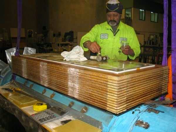
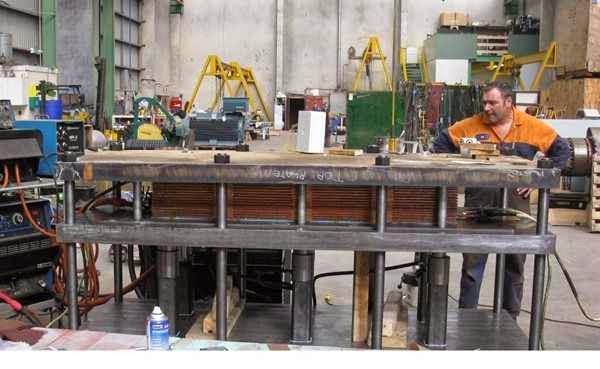
Wind Turbine Generator Stator Stamping Lamination
↧
How to make a Frame 5 generator ‘new’ in 15 easy steps
Maintaining your unit in top condition begins with proper operation. During turbine overhauls, conduct routine electrical, mechanical, and NDE assessments and perform all associated generator maintenance. Take advantage of today’s upgrades when the economic equation points in that direction; extend your vintage Frame 5 generator’s life and possibly increase its capacity. With such enhancements, your classic will gain value and stand the test of time.
Here, engineers from TurboCare, which overhauls many Frame 5 generators each year at its shops worldwide, walk you through the key steps involved in rehabilitating a vintage machine to virtually as-new condition.
↧
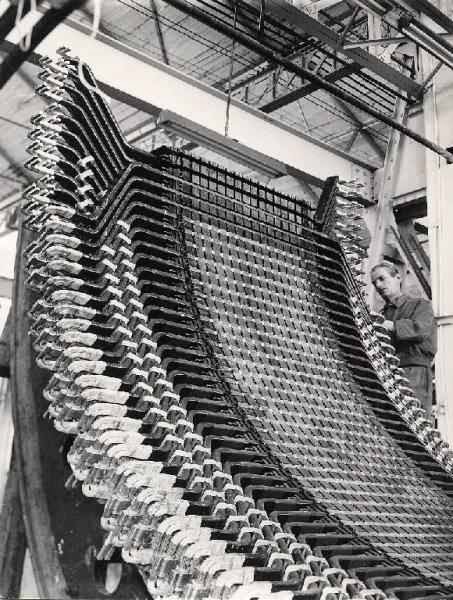
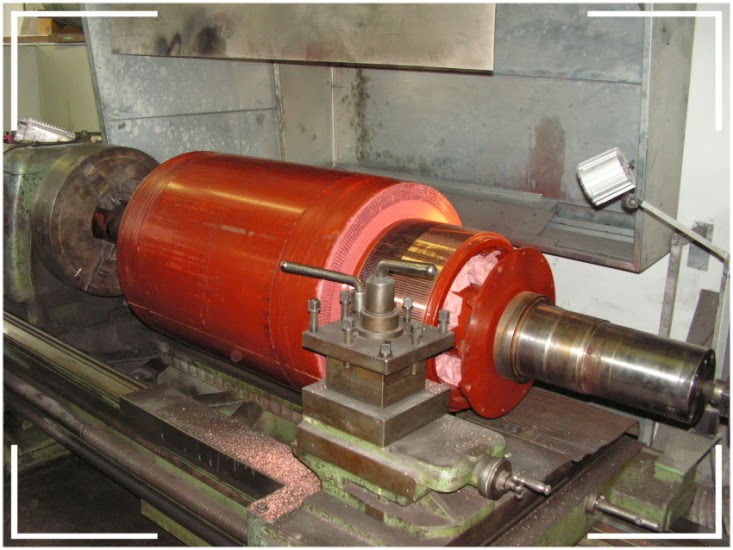
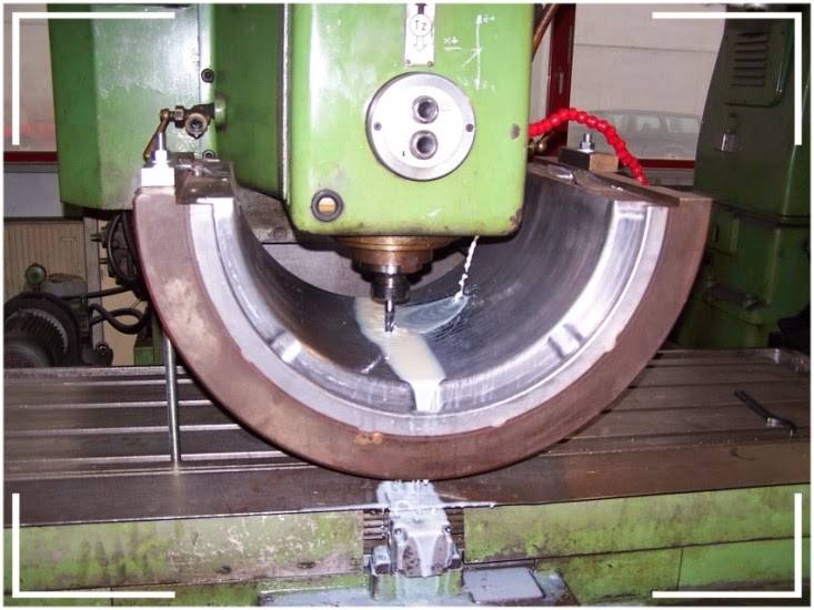
Ercole Marelli (the Company) - Alternator for Central Guide Falck - machining
↧
↧
Stator production © Enercon
↧
Pole pieces on the disc rotor: no tonal continuous geometry appropriate - © Enercon
↧
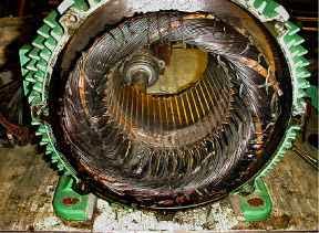
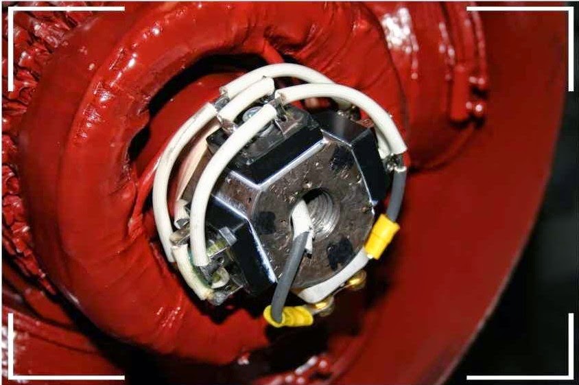
The decomposition of the motor burn out
↧
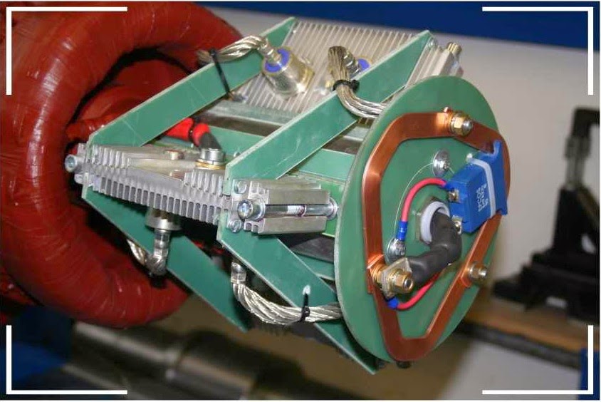
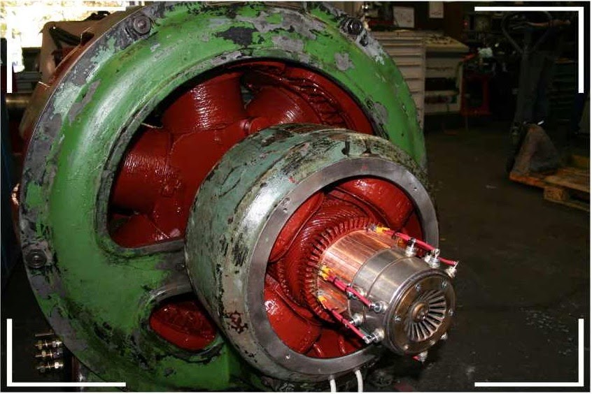
Generators Brushless Conversions from carbon brushes to co-rotating diodes
Generatorsof older designare fittedto the thenstate of the artwithbrush-typeexciter machines.
This is amoreorvinouslargeperturbation termfor your businessthat givesrise torepairs.Particularly unpleasant isthe pollution of themachineby means of electricallyconductivebrush abrasion.In connection with theoccurringcracks inthe course of timeinsulationThis representsan increased risk ofdamagewinding.
To increase thepermanent availability,weofferaconversion toco-rotatingdiodes(withremoval of allcarbon brushes)on.
In the future,thusalso setsalower maintenance,which reducesin principleto thebearing lubrication. Brushcontrol-andexchangeandcleaningmeasuresforbrush wearomitted.
Ourmechanical workshopand testingweare ableto carry outeverythingin our own factoryand modernizeyourgenerator.
In oldermachinesoften confronted with theproblem thatonlyhasthecollectorof the exciter machinedue to wearand variouseditsinsufficientfin height,sono further over speeding longer possible.
As an alternative torenewalof the collectorthereforeurgestheconversion to abrushless excitation, combinedwith all the benefitsof continued use,almost.Generatorsof older designare fittedto the thenstate of the artwithbrush-typeexciter machines.
This is amoreorvinouslargeperturbation termfor your businessthat givesrise torepairs.Particularly unpleasant isthe pollution of themachineby means of electricallyconductivebrush abrasion.In connection with theoccurringcracks inthe course of timeinsulationThis representsan increased risk ofdamagewinding.
↧
↧
Generators Bearing and Alignments
↧
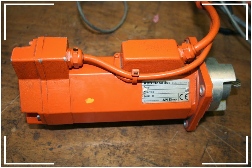
Servo Motor
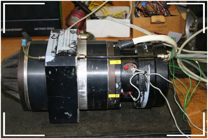
Servomotorsare an integral partofthemodernmachine toolandindustrial manufacturingtechnologywithvariouspositionings.
They requirefrom time totimea comprehensive serviceto meet thetile productforimportant,shortadjusting andpositioning timesandto ensure the absolutereliabilityandavailabilityover time.
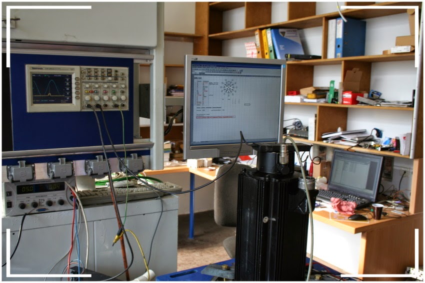
Wehave the meanstobring theseenginesand repair.This is documentedbytest report, whichismade possible by amoderntest bench.
The servo drivehasnext to thefavorableratio of power toweight anddimensionsand optimaltuningoftorquetoinertiamoment.The servo driveisusually designedforshort-term highoverload capability,which allows, with appropriate controlveryshortacceleration and deceleration times.These advantages makethe dissemination ofservomotorsisrising strongly.
Weareindependent from brandallthreebasic typesofservomotorsrepairedor checked.
DC servomotor:
The closedtypenoventilation,buta taxlossofheatvia the housingisprovided.Theprincipleoccurringat a direct currentmachinecarbon brusheswearisnotsoblown out,butremainsinthemachine.The resultingelectricallyconductivecarbondustmust be regularlyremoved bycleaning, otherwisearcing andBürstenkranz-or windinglossesareexpected.
tests:
No-load testwithmeasurement of current,voltage and speed
Rollingreview
Vibration measurementto check thebalancing quality
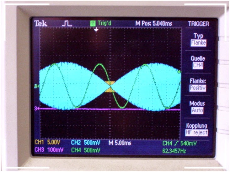
Incremental encoderandtachoteston the oscilloscope
AC servomotor:
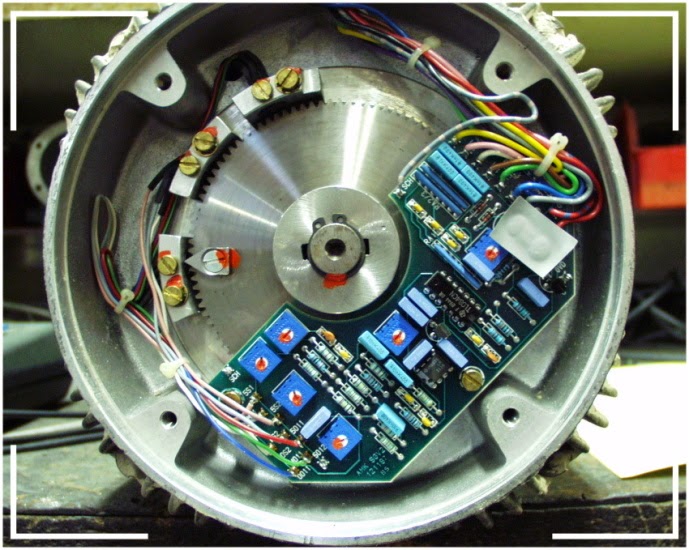
Tests and measurementsas in theDC-servomotorto thestampedmaximum speed,butno loadtest,additionalResolverprüfungmittlesoscilloscope.
AC-Synchro-servo:
Examinationandmeasurementsas inAC servomotor,additionallysettingthe position encoderon the oscilloscopeandcheckthe strength of thepermanent magnetrotorby means ofemfmeasurements.
In allservomotorsin addition to theinsulation resistance testandpuncture testis alsoan impulse voltage testtodetermine thestate ofwinding insulation.
Furthermore,a generalresistivemeasurement of thetemperature sensorandareview of allconnections(terminal boardorplug)is made.
↧
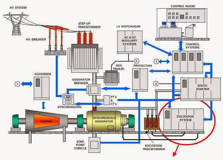
Construction of a power plant with synchronous generator
↧




.jpg)
..jpg)


+-+Alternator+for+Central+Guide+Falck+-+machining.jpg)





.jpg)
.jpg)
.jpg)
.jpg)
.jpg)
.jpg)
.jpg)
.jpg)
.jpg)
.jpg)
.jpg)
